
Converting a car to CAN
Or, ‘How I used Two Million transistors to replace four relays’.
My restoration of a a vintage electric car includes significant upgrades. Because the motor was beyond repair, I upgraded to a more powerful AC induction motor. This required a modern motor controller, and because hybrid and electric vehicles are hitting the scrap heap, I decided to move away from heavy lead acid batteries to modern lithium packs. All of these upgrades mean the stock dashboard electronics are obsolete; the stock speedometer is run off a cable, and the new motor does not have a cable connected to the shaft. Any sort of voltage measurement on the stock dashboard would be wildly inaccurate with the different cell chemistry and higher voltage.
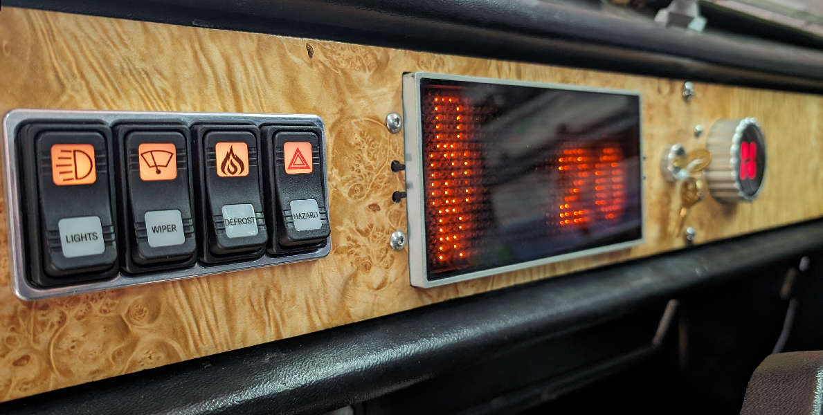
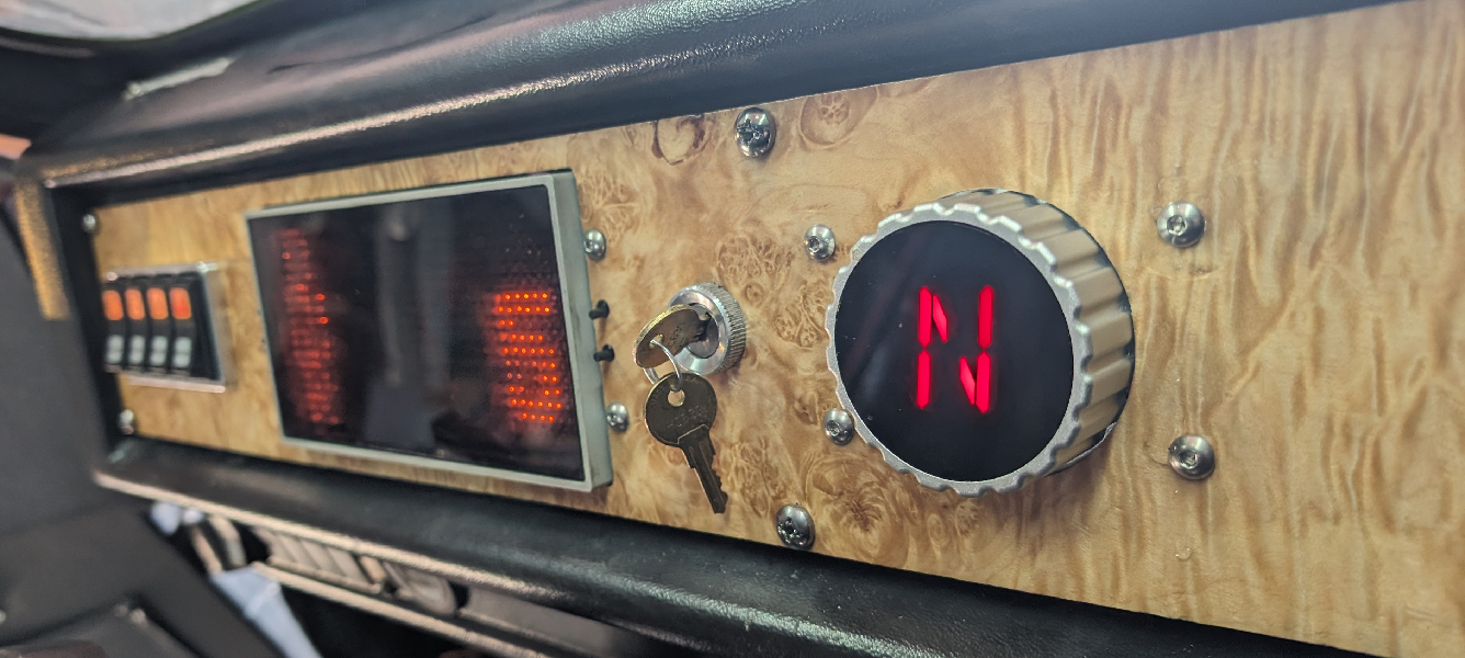
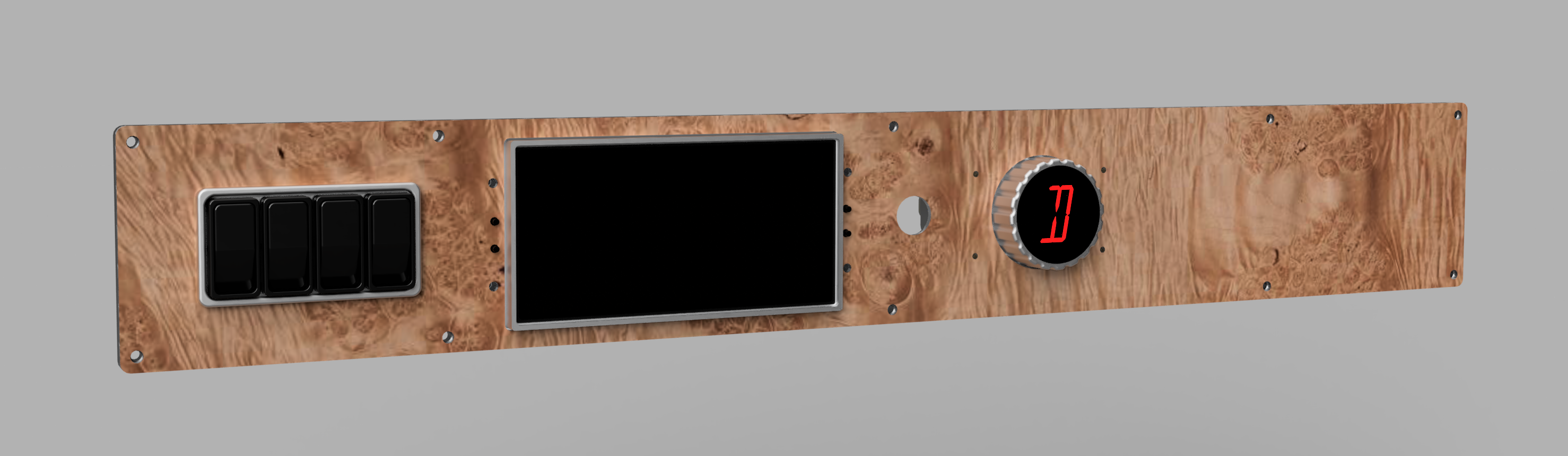
In short, to upgrade this car to modern electronics, the easiest path forward is to replace all of the electronics. But first, the pics of the finished dashboard:
A Comparison of Approaches
To describe what goes into converting a car to CAN, I must go over what the original schematic looked like. Here it is, on the left:
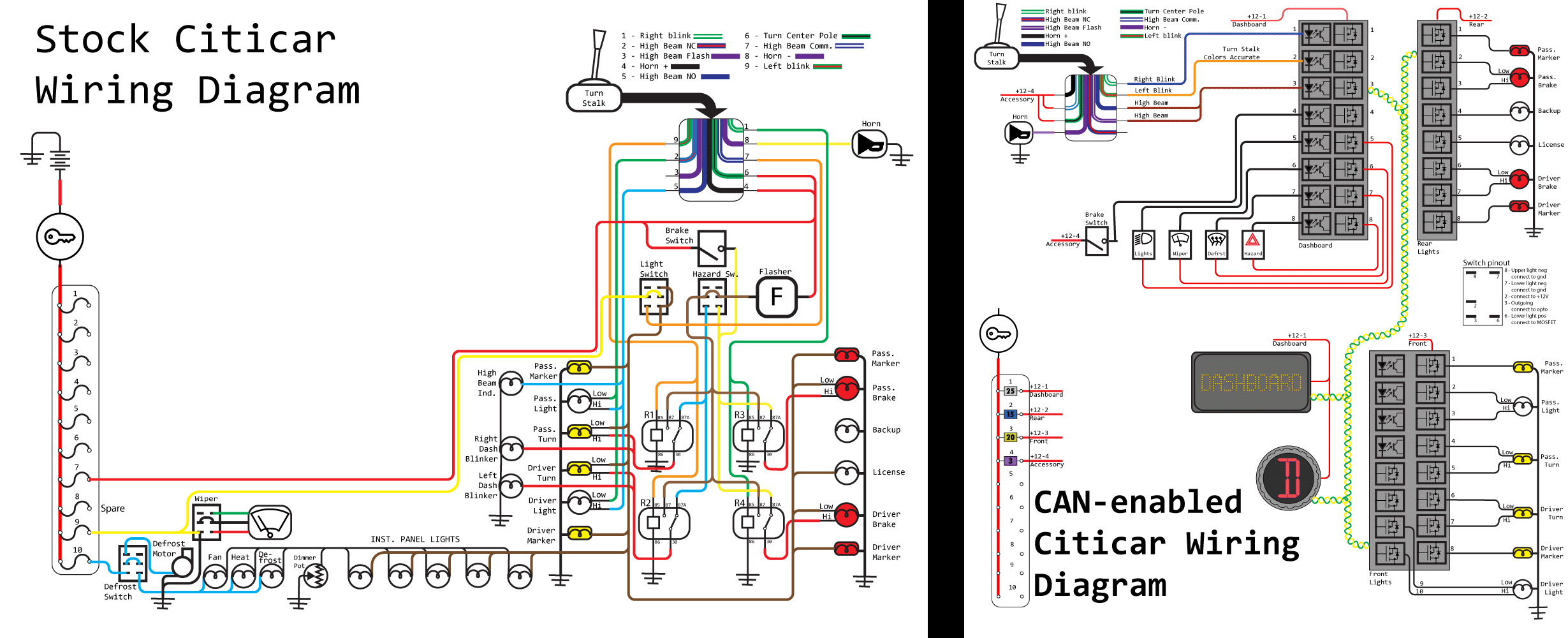
While this schematic neglects the high power electronics like the motor, contactor, and charger, the complete 12 Volt system is there. The brains of the operation is four relays. This, along with a ‘flasher’ unit – basically a bi-metallic strip that turns off when enough current is applied – is all you need to run a car. This schematic will handle hazard lights, turn signals, brake lights, and everything else a car is legally required to have. Throw some switches in there for the wiper and defrost and that’s all you really need in a car. Not shown is the speedometer, but you get the point.
The CAN version of this schematic is significantly different. Instead of relays, each of the lights on the exterior of the car – turn signals, marker lights, brake lights – are each connected to their own MOSFET. There are optoisolators to read the state of switches, a display for the speedometer and a CAN-enabled Reverse-Neutral-Drive switch. Here’s how I built each of those:
The CAN-MOSFET Board
The design of the MOSFET board has several requirements, including:
- There should be two CAN ports, because everything will be daisy-chained. Also, I’m using Deutsch connectors.
- Each device should have at least eight channels of output
- I’ll also need opto-isolated inputs to read switch states
- The device should be as small, or as thin, as possible. It needs to fit in a very small car.
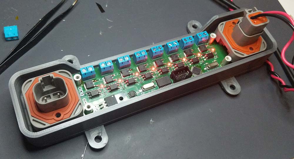
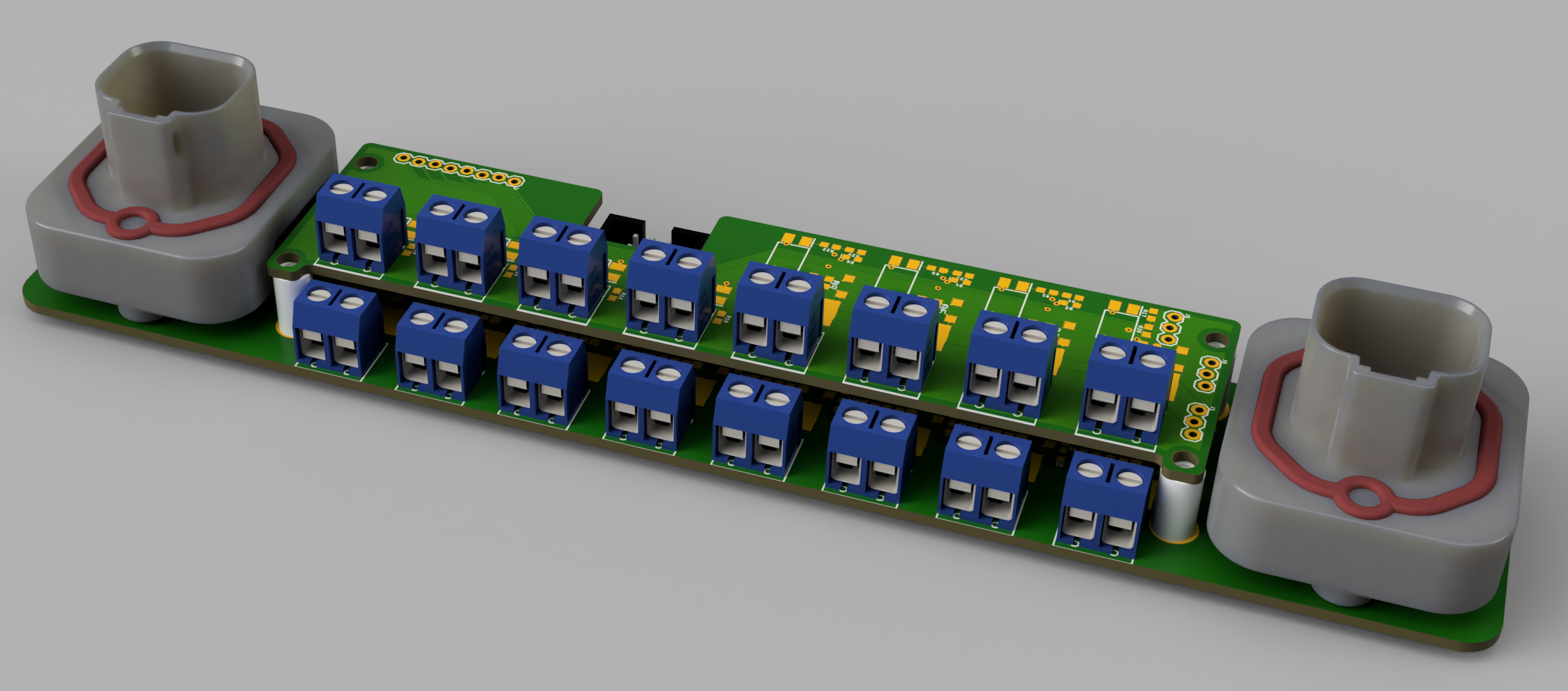
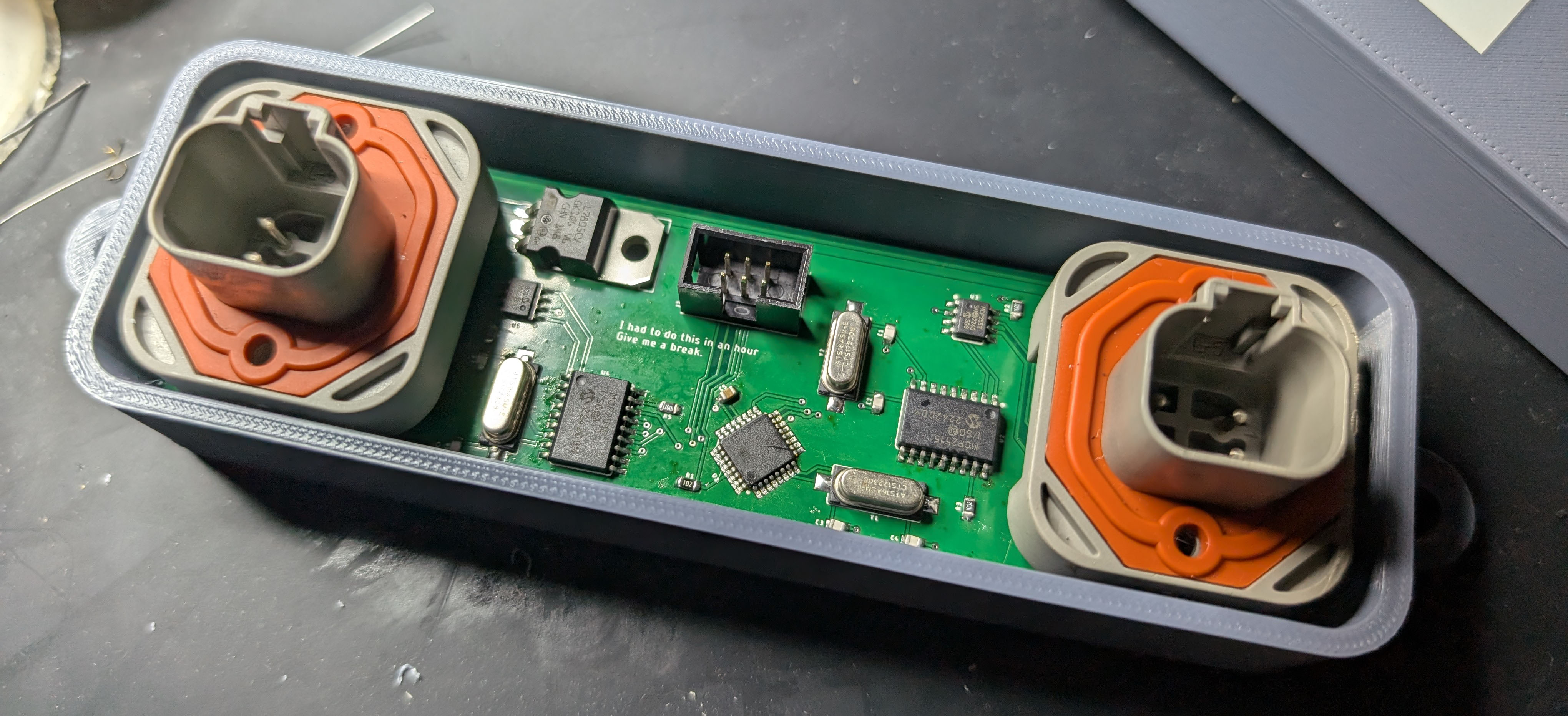
The design I came up with is below. There are two Deutsch connectors for power and CAN, along with a bank of screw terminals for each output. Yes, I’m aware the screw terminals aren’t the proper connector – ideally they would be soldered directly to the board or broken out onto a larger connector.
Also on this board is a ‘shield’ of sorts. The CAN MOSFET board has several different options:
- Without a shield, giving 8 MOSFET outputs
- With a 8-port opto input, giving 8 MOSFET outputs and 8 opto inputs
- With a 4/4 opto/mosfet shield, giving 12 MOSFET outputs and 4 opto inputs
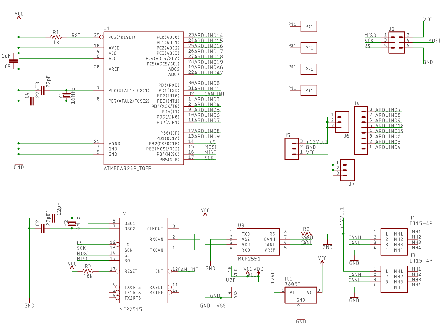
The circuit for the MOSFETs and optos are simple enough. For the ‘microcontroller and CAN’ part of the circuit, I settled on an ATMega328p, Microchip MCP2515 CAN controller, and Microchip MCP2551 CAN Transceiver. Yes, this is effectively an Arduino running my car, but with the proper application of watchdog timers, most concerns can be oblivated. See Jack Ganssle’s article on watchdogs for some introduction to this.
The Display
Click to play video
The only way for me to measure the speed of the car is by reading the motor RPM, dividing by whatever the gear ratio of the differential is, and multiplying by the wheel diameter of the wheels. I think pi is in there somewhere. I need a display, and the most basic LCD display simply will not do for this. To this end, I created an 18*39 LED display – that’s 702 LEDs – by writing a driver for the IS31FL3741 LED driver chip. This is the third time I have written a driver for this chip.
The CAD and PCB design for this display is just a column and row arrangement for the LEDs on one board. This is connected to a second board that holds an Adafruit Feather M4 CAN Express. Add some Deutsch connectors and it’s good to go. This is housed in a CNC aluminum enclosure, capped with tinted polycarbonate.
The main function of the display is that of a speedometer and odometer. This is done by reading RPM from the motor controller through the CAN bus and a bit of math. In addition to these two main functions, battery state and potentially range can be calculated from the CAN bus on the BMS controller. Of course, as the CAN bus is wired into the BMS, motor controller, and charge controller, I have access to any data I could ever want, accessing it is just a matter of coding it up.

The Shift Knob
Click to play video
The motor controller has inputs for Drive, Neutral, and Reverse that need +12 Volts to turn the motor in that direction. Because all my lights are CAN-enabled, I will also need to somehow present the state of the ‘shift knob’ on the CAN bus. The most obvious solution to this problem is to simply read this state with an additional optoisolator circuit. I did not do this. I created something much cooler
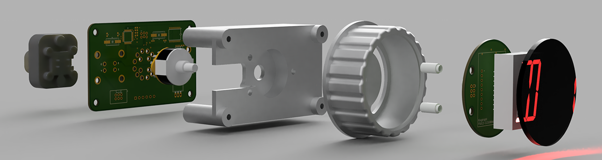
Above is the exploded view of my shift knob. It is a three-position rotary switch. Underneath the face of this knob is a 16-segment LED that shows ‘D’, ‘N’, or ‘R’, depending on the position of the switch. This rotary switch has four different center poles (it is effectively four separate 3-position switches), one pole of which is used by the motor controller, and a second read by an on-board microcontroller. This microcontroller sends the state of the switch over the CAN bus and also drives the 16-segment display.
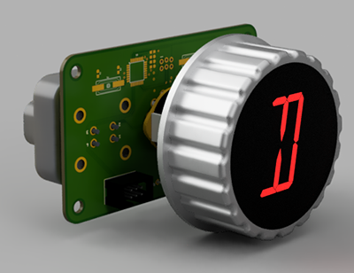
The really cool trick with this knob is the fact that the center indicator remains stationary as the knob turns. Turning the knob does not move the center indicator. It’s an effect that puts the ‘b’ in subtle, but is simply amazing when you notice it. It’s probably what I’m most proud of in this entire CAN conversion project.
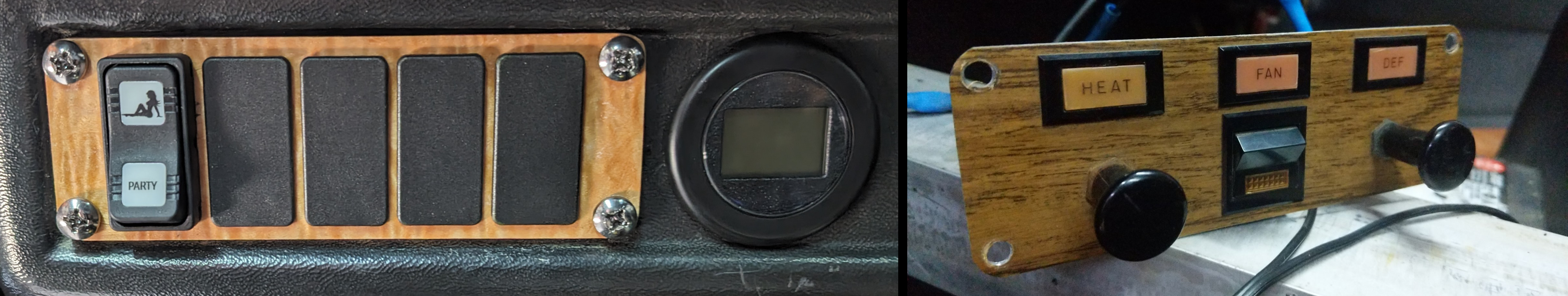
A Replacement for the heater controls
The stock Comutacar includes a ‘sub panel’ below the dashboard for what can generously be described as ‘environmental controls’. Actually, the HVAC system of the Citicar / Comutacar is hilarious, and deserves mention:
Motor cooling on the Citicar is accomplished by a twelve volt fan blowing cold air into the motor. This now-heated air is then recovered and sent into a manifold controlled by two pull knobs next to the dash. The heated air can be sent into the cabin, so everything smells like burning carbon brushes, or up to the dashboard, where it forms a rudimentary defroster. The only heat source in the entire system is the hot motor, there is no heat exchanger, and everything smells like blue smoke.
I will not be using the forced-air motor cooling and defrost system. The motor runs cool enough to not require cooling, and I am adapting a 12V / 150W Portable Car Heater to use as a defroster. This gives me space to add additional switches, or at least space for extra switches. I do not know what these switches will eventually do. One idea is to have a mode that changes the acceleration profile on the motor controller. Or a switch blinks the exterior lights randomly. Here’s a pic of the five-switch extension panel, along with the stock heater/manifold controls:
Integration with the rest of the car
One CAN bus will control the dashboard, lights, and the turn stalk indicator, but not everything. In an effort to reduce complexity on the CAN bus, I have broken it up into three parts: one for the battery, charger, and BMS, another for the motor controller, and the third for the dash and lights. The manual for the motor controller says I shouldn’t connect its CAN bus to the BMS and charger, so this will have to do. Here’s a pseudo-schematic of what I’m talking about:
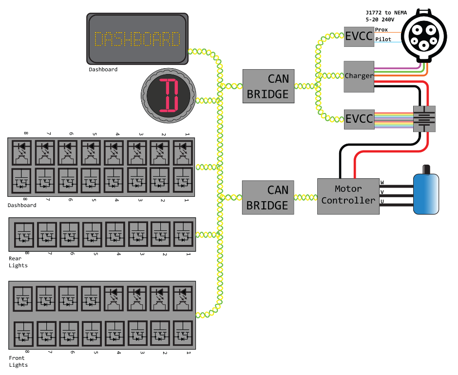
These CAN busses are tied together with a CAN bridge. Basically, it’s an Arduino with two CAN tranceivers. The microcontroller can read and write to each CAN bus it’s connected to. With a little bit of code, I can shuttle data across the bridge, even translating it to different data. Here’s the CAN bridge:
Putting it all together
The stock Citicar dash is a single piece of 1/8” aluminum screwed onto the plastic dashboard with the help of clip nuts. These nuts are terrible to install, they fall off constantly, and they really don’t secure the dashboard to the car very tightly. For my dashboard, I’ve gone a different route, with a piece of 1/4” waterjet aluminum physically bonded to the plastic dash with a combination of glue and fiberglass.
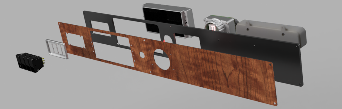
To this 1/4” aluminum ‘backer plate’, I attach a 1/8” aluminum ‘front piece’ to which most of the components are mounted to. The ‘dashboard CAN MOSFET device’ is still bolted to the 1/4” backer plate, but everything else - the shift knob, display, ignition switch, and aluminum switch bezel - are attached to the 1/8” aluminum front piece.
To give the front piece a little more class, I bought a long piece of maple burl veneer and attached that with contact cement. It looks amazing. Here’s the render of the final product, and a crude assembly diagram:
All of the files used to build this are available in the repo for this project.