
You can find an image gallery of all the pics here
1980 Citicar / Comuta-Car, Restoration
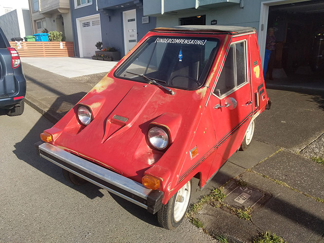
In the late 90s or early 2000s, right after I got my drivers license, I needed a car. I went to a convenience store, picked up an AutoTrader, and started leafing through the thinly printed pages. One ad caught my eye: a rare, weird, angular electric car from the 1970s. This was my introduction to the Citicar, a street-legal golf cart with ABS plastic body panels. It was glorious, and by far the coolest car in a magazine that also featured old Chargers sitting on blocks, one or two Mk4 Supras, first gen Miatas, and everything else that could be found in a 25-year-old AutoTrader. I’d like to repeat this for clarity: as a 17-year-old, a shitty plastic 70s wedge was cooler than the cars in Fast and the Furious. Now you know who I am.
The AutoTrader add offered the Citicar for a thousand dollars or so, and it said it only needed a few batteries to get the car moving again. Awesome. Impractical, though, because the Citicar has a range of about 30 miles and I grew up in the middle of nowhere. Did I really have the skills necessary to get this car on the road? This car would just end up being a money pit, right? In my youth I was far too cautious, the gravest mistake anyone can make.
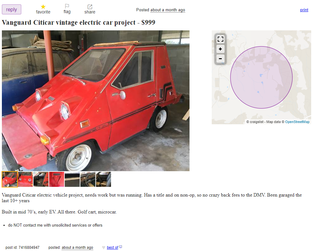
Fast forward half a lifetime and I’m in the middle of a COVID lock down. I have a job, I have money, and again I found one of these weird plastic cars on Craigslist being sold for a thousand dollars. It’s time to do this, I guess.
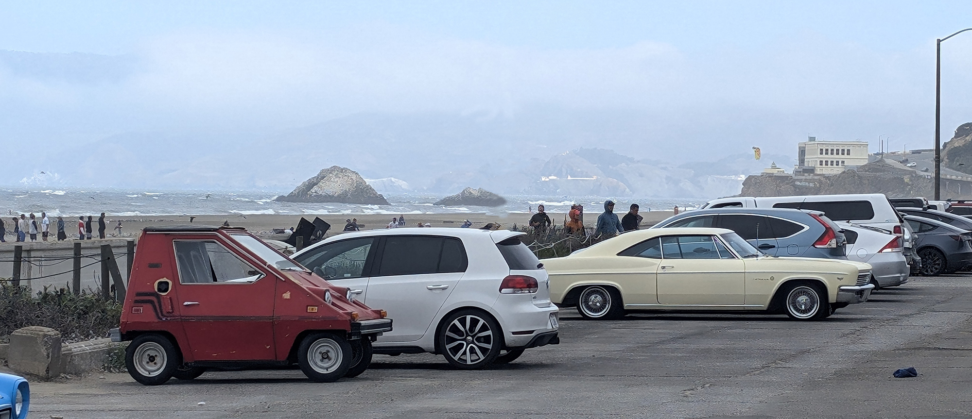
This is a log of the restoration of a 1980 Comuta-Car, acquired from a Craigslist ad in Fresno. It took far too long and cost far too much money, but this is the coolest car I could possibly own.
Part 0, Acquiring the car
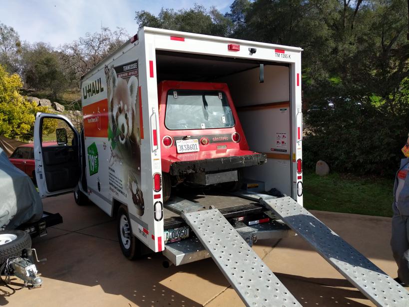
The car was bought off of Craigslist in Coarsegold, California, about half an hour north of Fresno. The bill of sale says $200 in the hope this will eventually be in a Lemons rally. Getting it to my SF garage involved driving out to Fresno, picking up a 10’ UHaul box truck and car trailer, and bringing it home through Gilroy.
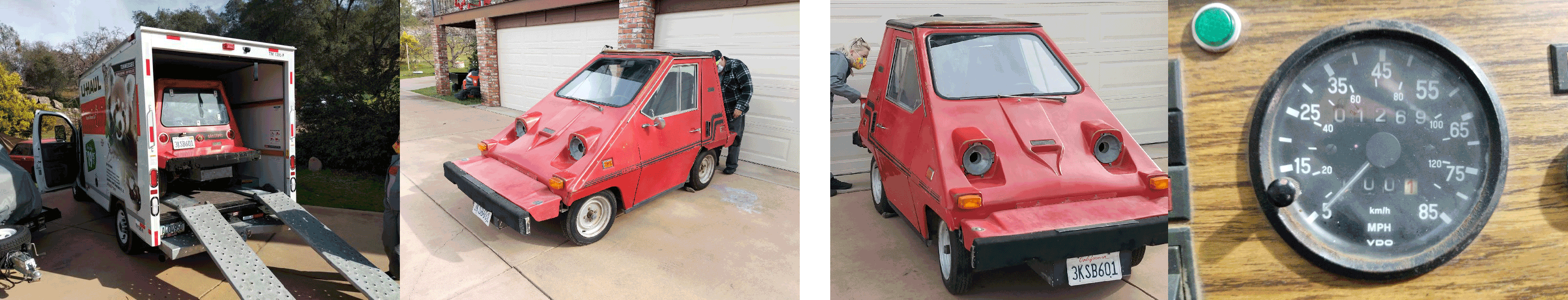
Tips and tricks for acquiring a Comutacar: It barely fits in the back of a 10-foot UHaul truck. The easiest way to get it home is to rent a 10-foot UHaul, buy some ramps at Harbor Freight, and get three people to push it up into the truck. Without the batteries it only weighs ~700 pounds. No, you don’t need a trailer, in fact a citicar does not fit on a UHaul car trailer because the wheelbase is too narrow.
The plan, at the time, was to fix the wiring in the car, put some batteries in, and see if the car can go around the block. Maybe to the grocery store. After that, I would assess putting some bigger lithium batteries in, and the possibility of upgrading the motor. An easy job, right? Should only take a few months.
Part 1, Teardown and I found a motor controller
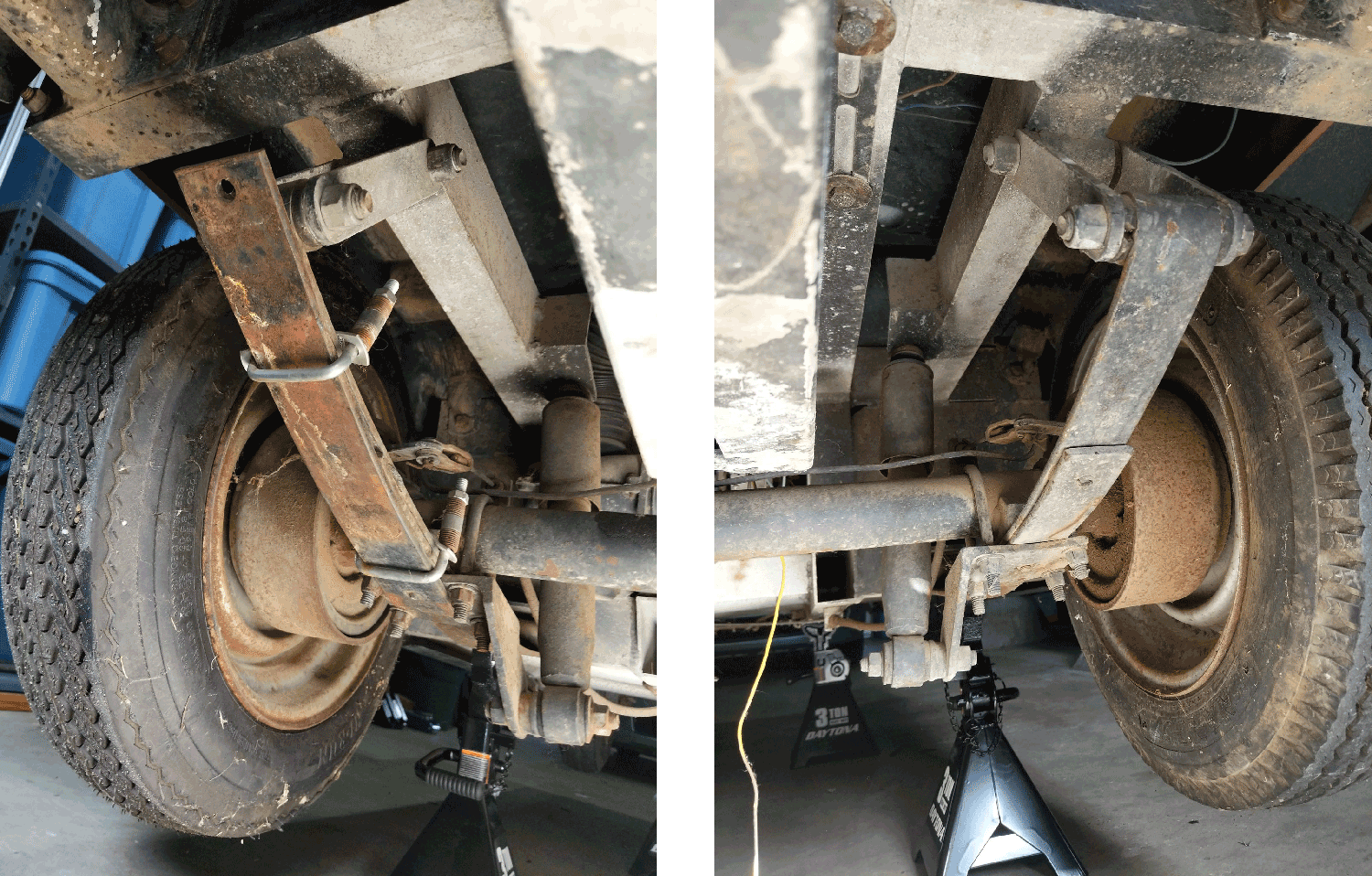
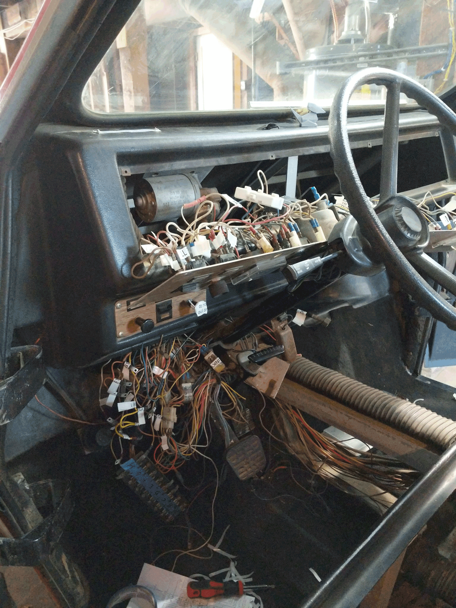
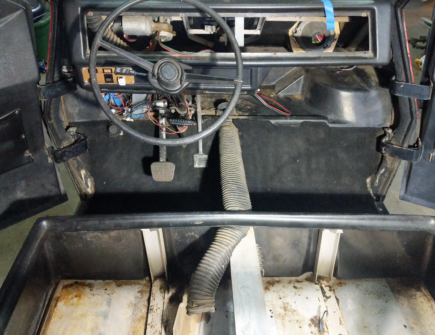
Week 1 began with getting it up on jack stands. This revealed some weirdness with the back suspension. For some reason, half a leaf spring was bolted to the driver’s side suspension. I don’t know what’s going on there. The wiring under the dash was a mess, and the 120 Volt input was highly dangerous so that was torn out to be replaced with all new wiring.
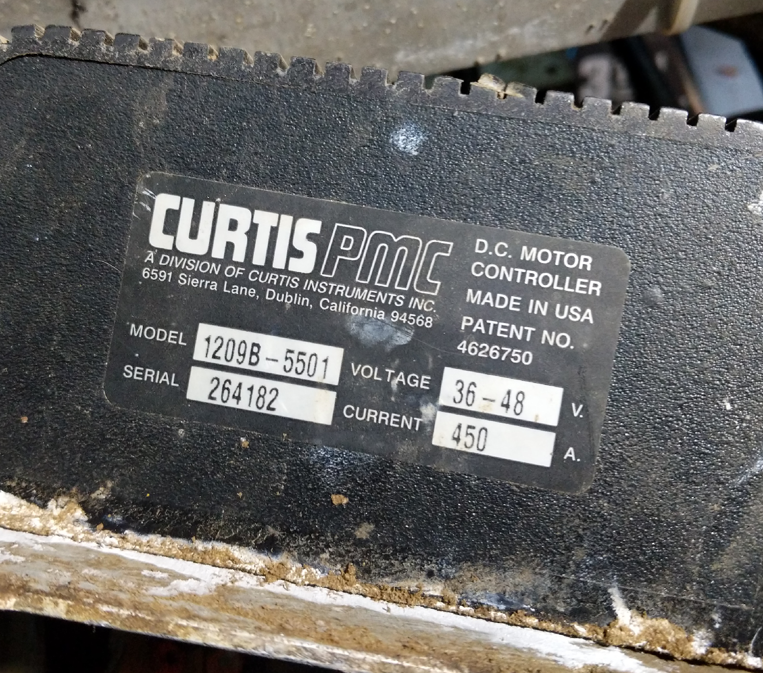
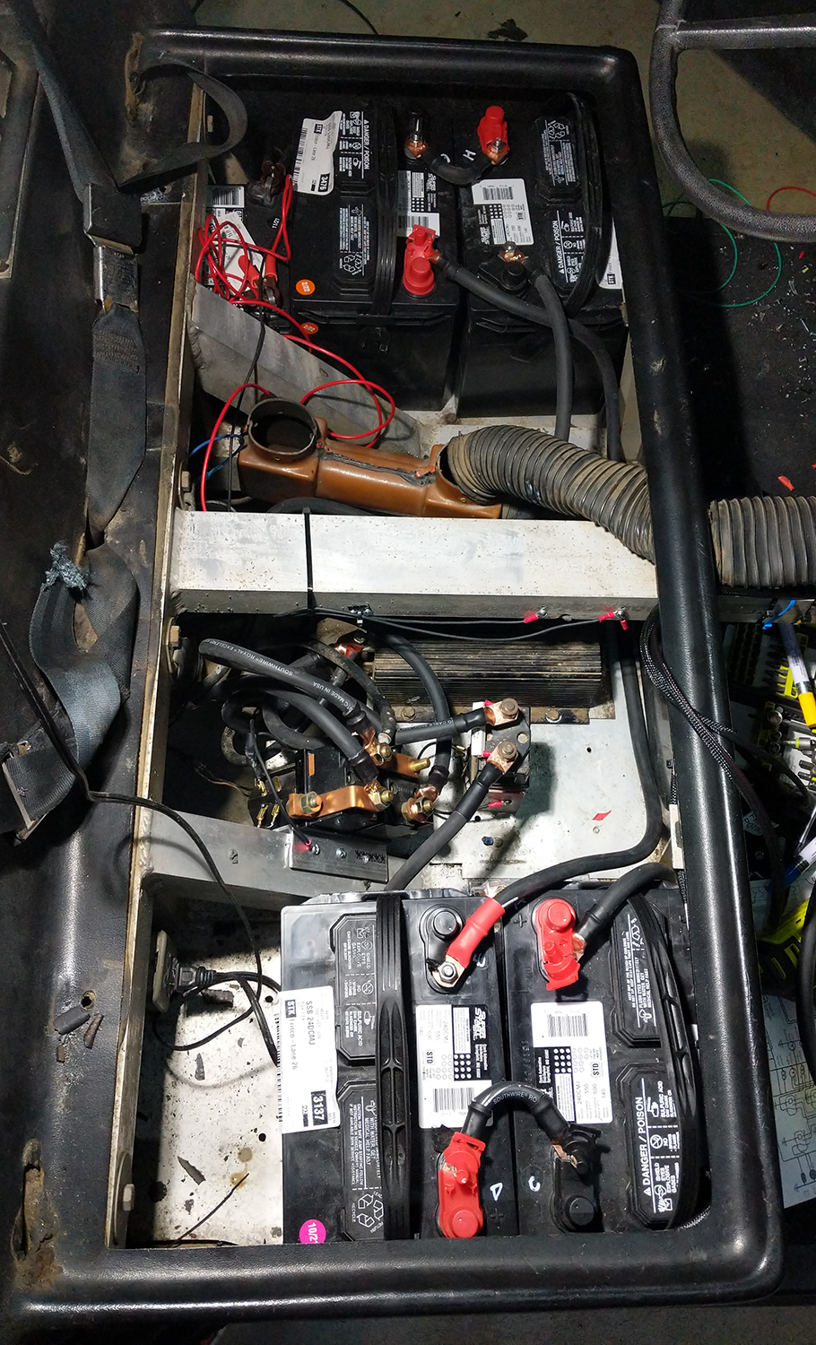
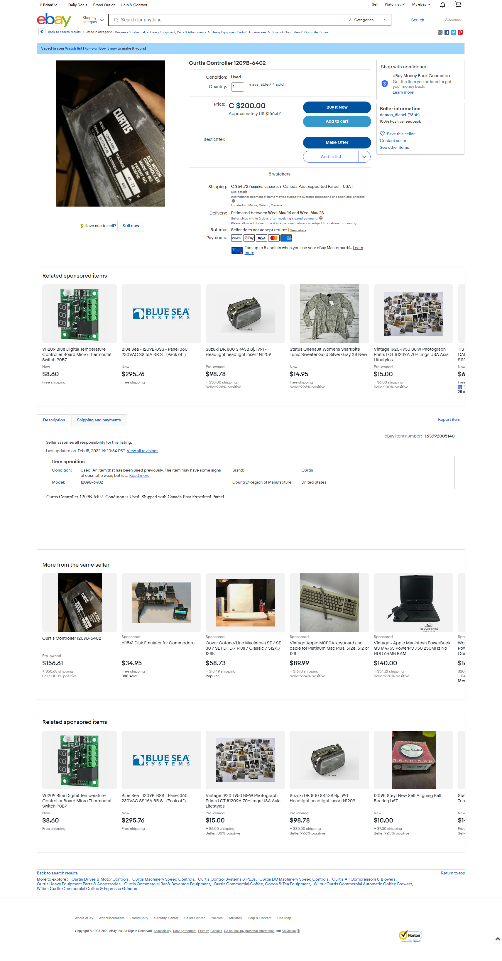
During the teardown, I was looking at this weird box right next to the motor. The car still had the original contactors (the old “speed controller”), and I had assumed the previous owner was still trying to use this. Not so, because that weird box was a brand new motor controller. To reiterate, I found an unused motor controller worth $1000 in a car I paid $1000 for. I bought a motor controller and got a free car.
Given the serial number on the unused motor controller, a few parts on the wiring harness, and the oral history of the car from the seller, I think I can put together a reasonably correct history of this car. Sometime after 1993 and before 2000, the car was in Palm Springs where the owner decided a refurbishment was in order. This person had the knowledge to walk into NAPA auto, but not the skills to put those parts together. The last time it was registered was in 2000, after which it was moved to Coarsegold, half an hour north of Fresno. In 2022, I brought it to San Francisco where it was restored.
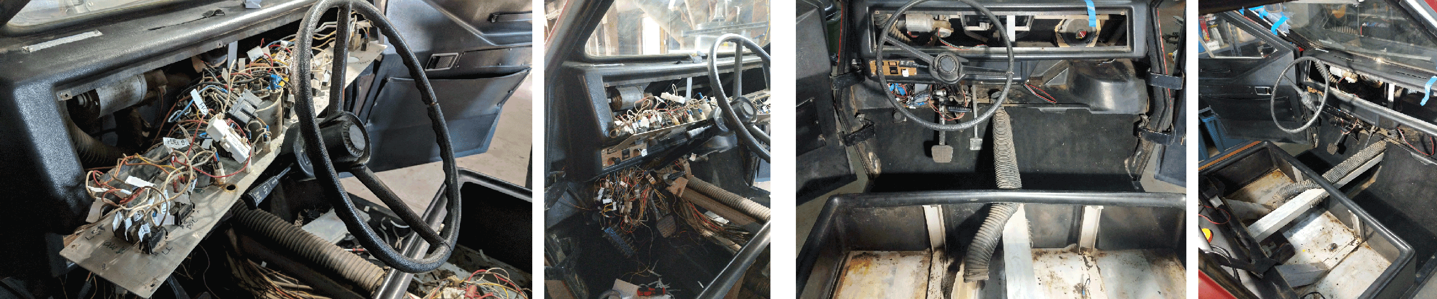
After a few days of reverse-engineering the wiring, we determined the best course of action would be to tear out all the wires and rebuild the entire electrical system from the ground up. This gave me an opportunity to clean out twenty years of detritus in the under-seat compartment. This was a weird, sticky goo that cleaned up with soap and water. I also found a mouse nest inside the ventilation/cooling manifold; this manifold was removed, cleaned in the dishwasher, and reinstalled.
With that done, the project moves onto re-wiring the electrical system. This will be guided in part by the schematics found in the CommtaCar service manual but updated for a modern fuse panel.
Part 2, Rewiring the dash, or, I know how to hotwire my car.
Because the car didn’t come with keys – or rather the last owner couldn’t find the keys – a new ignition switch was in order. The standard ignition switch for the Citicar is a Cole Herse 9577-BX, in stock at my local O’Reilly Auto for $15.99. The rest of the dash electronics will remain stock. Also, I ordered a new lock for the rear hatch, because again, no keys. This was off of Amazon, a ‘Disc Tumbler Cam Lock with 7/8” Cylinder’. An inspection behind the door card revealed the door lock will be harder to replace
Rewiring the dash began with simply pulling out all of the old wiring. There was nothing that could be salvaged out of that rat’s nest. I ordered a new fuse panel (Eaton / Bussmann 15305-2-2-4) for 10 mini fuses and five SPDT relays. The original wiring used 10 fuses, two DPDT relays, and a blinker module, so everything should work.
Also bought with the fuse panel were a bunch of crimp terminals and various paraphernalia. This was mounted in a new, 3D printed panel just under the dash. The STLs for the fuse panel can be found here.
Because I’m restoring a car in 2022, of course there would be a shortage of crimp terminals. There is a ‘semiconductor shortage’ as I write this, but this doesn’t tell the whole truth: we’re out of all electronics. The Eaton/Bussmann fuse panel I wanted was out of stock everywhere, so I acquiesced and bought the one with bussed relay contacts. We’re out of terminals, and earlier this year I noticed everyone was out of crystals. I simply can’t buy a 12MHz crystal in the package I need right now. The ‘semiconductor shortage’ isn’t just semiconductors, and it’s truly awful.
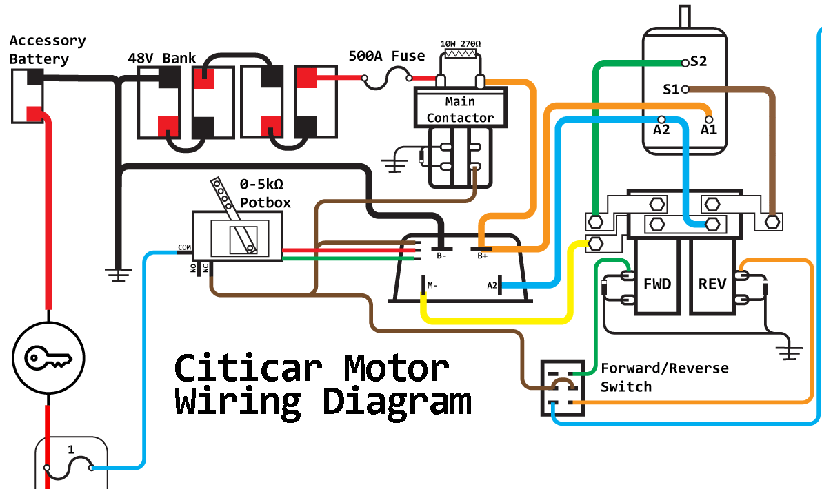
Wiring the dash started with a new schematic based on the wiring diagram in the Citicar / CommutaCar service manual. The old manual was a confusing joke. The documentation for the turn signal stalk is a mess, so I replaced the old turn signal stalk with a new one from a 1977-80 Triumph Spitfire. As a bonus, the high beam switch in the new turn stalk actually works.
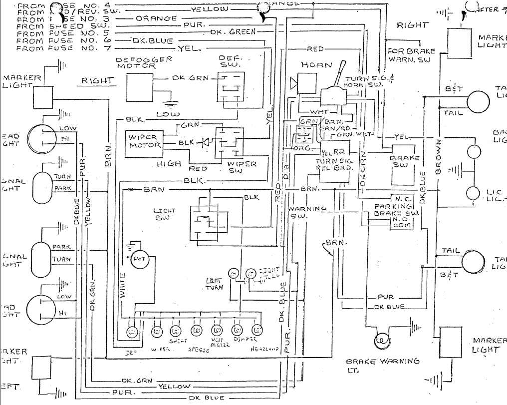
With the fuse panel, a new turn signal stalk, a bunch of 14ga wire, and a boatload of connectors, I was ready to rewire the dash. For this, I had to reverse engineer the Citicar service manual schematic, which was unreadable. The ‘official’ Citicar schematic shows all the flasher/relay ‘logic’ behind the turn signals as happening in a ‘Turn Signal Relay Board’, which is not documented anywhere. Wires are just missing on the service manual schematic. I had to re-make the schematic. Compare a section of the old and new schematics, both showing the same bits of the entire circuit:
A comparison between the original service manual schematic, and a schematic done by someone who can draw:
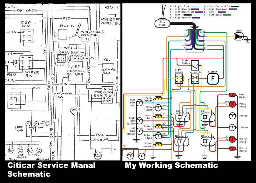
The difference is stark. The old schematic was unreadable not only because some wires were cut off from many generations of photocopying, but also because of a mysterious ‘turn signal relay board’ that is completely undocumented.
After a false start and a few obviously crossed wires I was able to get the majority of the dash wiring done. There are a few bits of weirdness to the Citicar schematic, though; the headlamps are switched through two switches, the dash switch and the turn stalk. Because of this, only the top position of the dash switch turns on the headlamps, which are then switched through high and low beams with the turn stalk. The ‘lower’ setting of the dash light switch only activates the running lights, without the headlights. This is weird, but I suppose it’s DOT compliant, it should be close to what the original wiring should be, and it’ll work.
With the dash wiring completed, I turn my attention to the power electronics and getting the motor turning.
Part 3, Motors, Motor Controllers, Batteries And An Entire Year.
Wiring up a few switches and a fuse box is easy. Very easy, and there’s no way it could take literal years. The motor and controller were another story.
The original “controller” for the car was a bizarre resistor and contactor design. This setup reduced the throttle pedal to a three position switch; the first throttle setting was 24V, the second setting was the full 48V pack with a current-limiting resistor that was actually a gigantic piece of nichrome wire, and the third setting was the full 48V pack. This was fed through a main contactor and a forward/reverse contactor from a golf cart. My Citicar came with an uninstalled upgrade in the form of a Curtis controller designed for golf carts.
With the 12V electronics done, the goal was to wire in the motor controller that came with the car and possibly take it down to Ocean Beach Cars and Coffee. As noted in Part 1, this car came with a motor controller, a Curtis 1209-5501 rated for 48V / 450A. Taking notes from the manual for this controller, I finished the schematic and wired the whole thing up. Additionally, because I didn’t want to deal with the old forward/reverse contactor (it was chooched), I purchased a new F/R contactor off of eBay for $100.
After wiring everything up according to the controller manual, I turned everything on, and…. nothing. The motor didn’t spin, and following the troubleshooting steps in the controller manual discovered the controller was faulty. I could have the controller rebuilt for $450, but another used controller is available on eBay for $200. This “new” controller is a slight upgrade over the controller that came with the car – the eBay controller goes up to 72V. Judging from a few Citicar message board threads and the fact I live in the hilliest city in America, this should be a welcome upgrade.
The problem is, when I got the new 72V controller, it didn’t work either. I now had two broken motor controllers, and a great lesson on how expensive thrift is. After sending the new controller out for a rebuild for $450, but after that, I had a working controller.
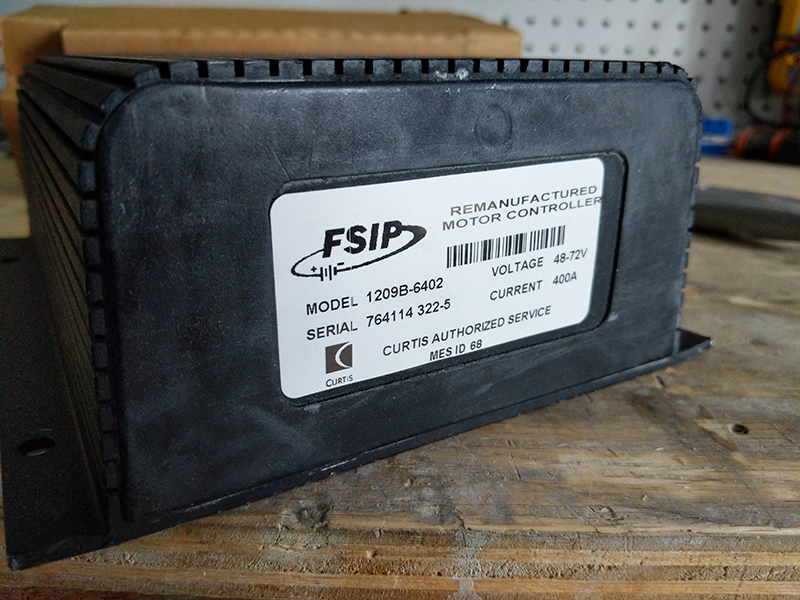
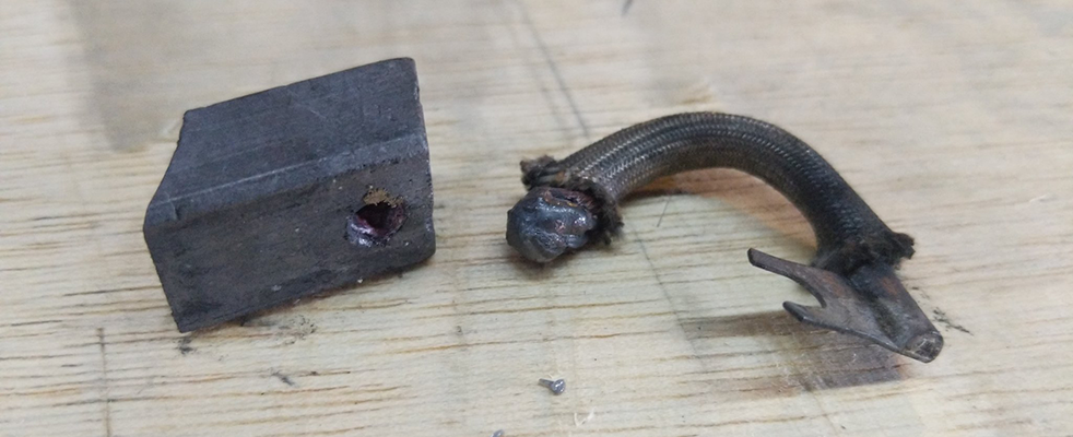
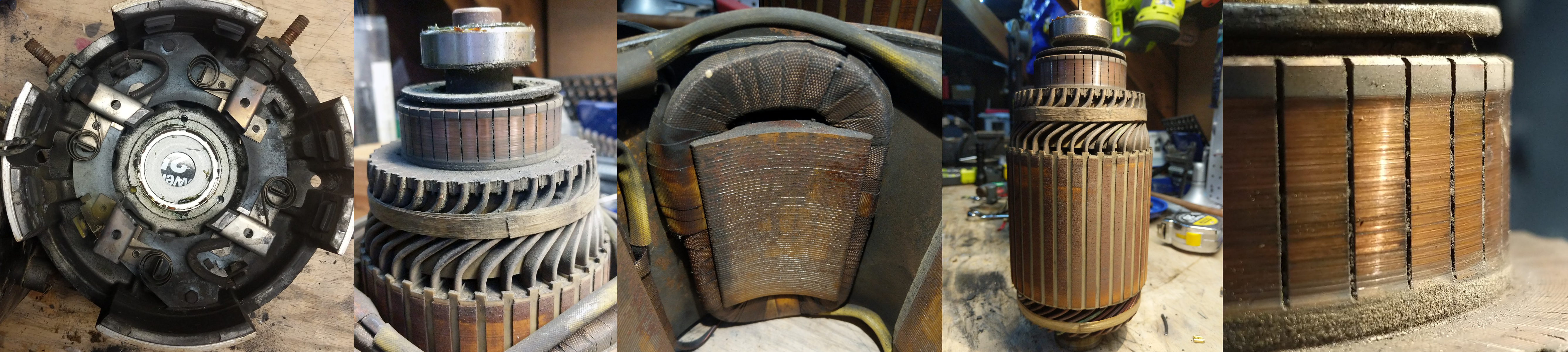
With the new controller tested and confirmed working, I still couldn’t get the motor to turn. I tested everything, including the forward/reverse contactor, and everything checked out. The problem had to be the motor itself, and opening the little rubber doors on the motor confirmed this assumption. The brushes for the motor were chooched. Two out of the four brushes were disconnected from their lead wires:
I had two options: replace the brushes ( forty bucks ) and hope everything else is okay, or replace the entire motor ( two grand ). I, of course, chose the less expensive option, which seems to be a recurring theme in this build. This did not come back to bite me in the ass at all.
After pulling the motor out, I had some idea of what the motor mount and spline looked like. At least now the motor is easy to work on and I can assess my replacement options.
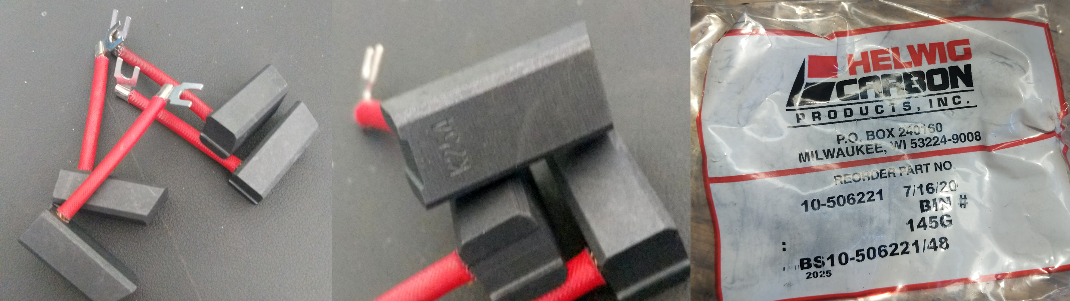
The new brushes were installed (0.5” x 0.625” x 1.437” carbon brushes, part number 10-506221), and I bolted the motor back onto the diff. Wired everything up again, and….. nothing. Not a damn thing. The controller was confirmed working with the ‘motor tester menorah’, and the motor was confirmed working by wiring it up directly to the battery. Hey, at least the new brushes worked. This only meant the forward/reverse contactor as being the problem, which is odd because I can hear it clicking when changing directions on the dash. Turns out this wasn’t sufficient, and I needed a 12V F/R contactor.
A hundred bucks later, and I had a forward/reverse contactor with a 12V coil voltage. The wheels spun, I dropped it down off the jacks, and the car barely inched along. There simply wasn’t enough current going to the motor. The car moved and I was able to pull it out of my garage and into the driveway, but there was simply no power. Zero torque. The motor was just bad.
I would like to reiterate the process of getting the wheels to turn, in bullet point format:
- The car came with a Curtis controller for golf cart motors
- I install everything, nothing happens, because the controller was dead
- I buy a new controller on eBay
- This controller doesn’t work, send it in for repair
- Install the new controller, still doesn’t work.
- Turns out the motor is bad, somehow
- Replace the brushes in the motor
- Wire everything up again, it still doesn’t work
- Replace the main contactor, now I can at least hotwire the car
- The forward/reverse contactor doesn’t work, replace that too.
- Now I can control the car with the throttle pedal!
- The motor has zero torque. The motor is broken beyond repair.
- After months of working on this, say fuck it
From here, I had a few things to consider. The motor could be faulty, but fixable. Looking at the actual manual for the GE motor showed the ‘clocking’ - the positioning of the brushes along the commutator - could not be changed outside the factory. I had assumed the windings were good, and on paper everything should have worked. But it didn’t. It was time to say fuck it.
This was the lowest point of the project. There was nothing I could do except replace the motor. And if I’m going to do that, I might as well go big. The car will now have an HPEVs AC-12 motor from Thunderstruck Motors. The AC-12 motor – HPEVs link – is a motor made for the golf cart industry, but on a scale that’s a bit crazy. The stock motor in my comutacar was 6HP; the HPEVs motor will max out at about 36HP. This gives me a lot more torque for the San Francisco hills, and a few videos on Facebook lead me to believe the car will eventually do wheelies. The motor kit cost about $3k, but that also gets me a new motor controller.
The new motor also required a new motor mount. This was designed in Fusion360 and sent to PCBway for manufacturing. I highly recommend this way of manufacturing – it was less than 10 days and $250 to get a brand new motor mount.
After two or three different motor controllers, pulling the motor out of the car for new brushes, bearings, and everything else that’s removable, I finally had the setup I wanted from the beginning. It’s a hugely powerful motor that will easily conquer any hills, and the CAN interface allows for easy integration with modern batteries, chargers, and the electronic dashboard.
Mounting the motor to the axel with the new motor mount was astonishingly easy and cheap. I have nothing but good things to say about getting your one-off CNC work done at a random Chinese vendor.
Because the stock motor is broken beyond repair, I have upgraded to an AC motor from HPEVS. This is attached to the transaxle with a CNC’d aluminum faceplate mentioned above. Combined with the Curtis F4A controller, this motor will operate on 60V and give me about 30 horsepower, five times as much as the stock GE motor. Because it’s an AC motor, I’ll also get full torque at low speed, a must for my eventual goal of driving up and down Clipper St. in San Francisco (an 18.5% grade!)
The charger and BMS for the system is a TSM2500 and Dilithium Design BMSC allowing for charging over a J1772 port installed earlier.
The battery for the system is a single pack taken from a Chrysler Pacifica Hybrid. This pack provides 2.6kWh and is rated at 400A continuous, matching the expected max draw from the controller. Because I am running the motor at 60V, I can start with one battery pack and wire additional batteries in parallel to get more range – the only thing needed for each additional battery is a Dilithium BMS Satellite for each additional pack.
Battery cooling is an open question. Ideally, all batteries should be cooled (and heated) so they don’t become bombs. However, the Chrysler Pacifica batteries are very overspecced in their C-ratting; each battery can easily withstand an 800A current draw intermittently, and my motor controller is rated for only 400A. I do not expect to constantly draw 400A from the batteries, an average trip will be a current draw of about 150 to 200A. The battery should be fine, and a few forum threads seem to confirm this notion. Cooling should not be needed because of the low current draw, and heating isn’t needed because I live in San Francisco. It’s always 60 degrees here. At most, I would attach a thermal interface material to the bottom of the batteries and attach them either to the aluminum body, or an aluminum plate in the repurposed battery bays.
BMS Connectors
The connectors are listed below:
Dilithium BMSC
| Connector | Connector Part Number | Terminal Part Number |
|---|---|---|
| Cell Harness Connector | Molex 43025-1408 | 46235-5001 |
| Thermistor Connector | Molex 51110-1060 | 50394-8054 |
Chrysler Pacifica battery / KET 040 III Series connectors
| Connector | Connector Part Number | Terminal Part Number |
|---|---|---|
| 12 Pin Connector | KET MG653012 | ST730770 |
| 16 Pin Connector | KET MG653019 | ST730770 |
The connectors for the Pacifica battery can be easily obtained on AliExpress for $15/10pcs.
These connectors will be used instead of the EV West Pacifica Battery Harness, because crimping your own purpose-built wires reduces the number of adapters and converters required.
But with everything together, I finally had a car that could make it up the slight grade of my driveway:
Of course this doesn’t mention that in between troubleshooting the motor and buying a new one, I had given my car a CAN bus with a new gauge cluster. Thus:
Dashboard Confessionals (Screaming Infidelities)
Gauge Cluster & Digital Dash & Upgrading to CAN
My restoration of the Citicar includes significant upgrades. Because the motor was beyond repair, I upgraded to a more powerful AC induction motor. This required a modern motor controller, and because hybrid and electric vehicles are hitting the scrap heap, I decided to move away from heavy lead acid batteries to modern lithium packs. All of these upgrades mean the stock dashboard electronics are obsolete; the stock speedometer is run off a cable, and the new motor does not have a cable connected to the shaft. Any sort of voltage measurement on the stock dashboard would be wildly inaccurate with the different cell chemistry and higher voltage.
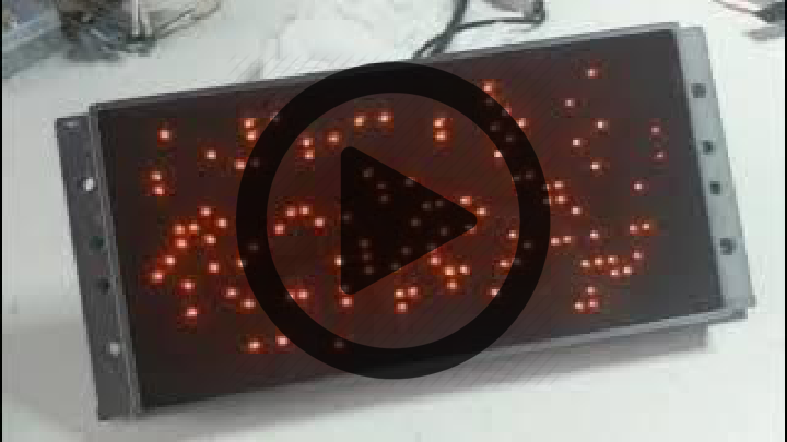
For a new speedometer, I have two options. The first is buying a CAN gauge I can program to display the speed. I don’t like this option because it doesn’t fit with the 1980s nerd car aesthetic I’m going for. The second option is to build a gauge cluster and program it to receive CAN messages. This took two attempts. My first attempt at a ‘digital dash’ consisted of a Planar Electroluminescent display ripped from a c.2000s Sun router. This is decidedly anachronistic for a 1980s nerd car, but if you squint it looks like something that should have been possible. Surrounding the EL display are flip dots for battery state-of-charge; I’m using flip dots because they will display the state of charge while the car is off. All of this was assembled into a 3D printed enclosure. I hated it. It didn’t look the part. The fit and finish was great, but it just wasn’t for me.
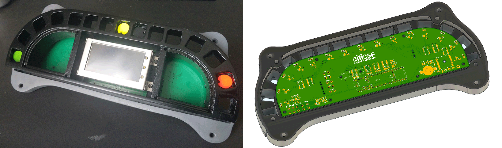
My second attempt at a ‘digital dash’ is effectively an LED display pulled out of a bus. It’s the most complicated device I’ve ever built and assembled.
A picture of the final Dashboard
A Comparison of Approaches
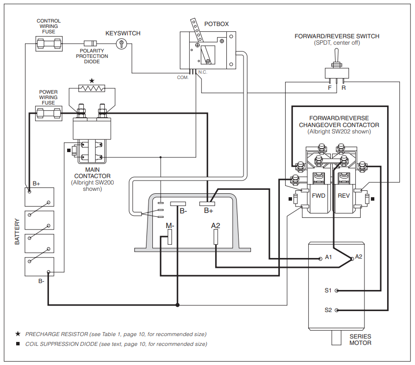
To describe what goes into converting a car to CAN, I must go over what the original schematic looked like. Here it is, on the left:
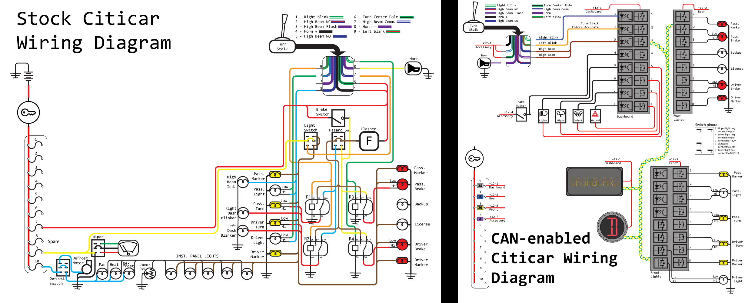
While this schematic neglects the high power electronics like the motor, contactor, and charger, the complete 12 Volt system is there. The brains of the operation is four relays. This, along with a ‘flasher’ unit – basically a bi-metallic strip that turns off when enough current is applied – is all you need to run a car. This schematic will handle hazard lights, turn signals, brake lights, and everything else a car is legally required to have. Throw some switches in there for the wiper and defrost and that’s all you really need in a car. Not shown is the speedometer, but you get the point.
The CAN version of this schematic is significantly different. Instead of relays, each of the lights on the exterior of the car – turn signals, marker lights, brake lights – are each connected to their own MOSFET. There are optoisolators to read the state of switches, a display for the speedometer and a CAN-enabled Reverse-Neutral-Drive switch. Here’s how I built each of those:
The CAN-MOSFET Board
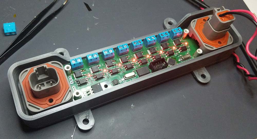
The design of the MOSFET board has several requirements, including:
- There should be two CAN ports, because everything will be daisy-chained. Also, I’m using Deutsch connectors.
- Each device should have at least eight channels of output
- I’ll also need opto-isolated inputs to read switch states
- The device should be as small, or as thin, as possible. It needs to fit in a very small car.
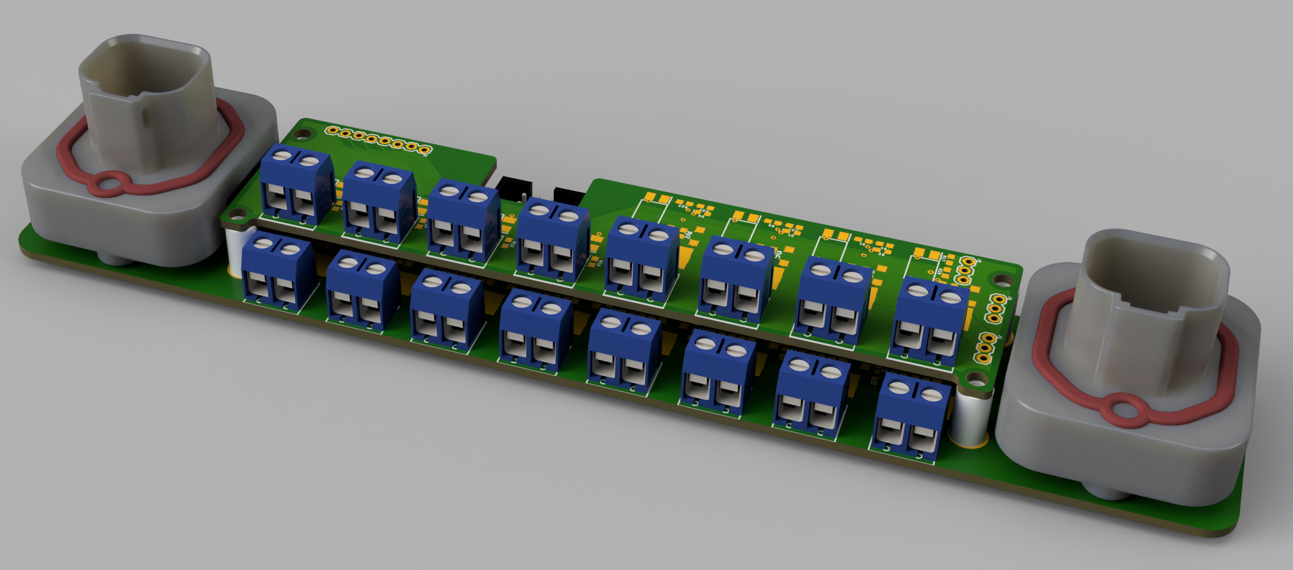
The design I came up with is below. There are two Deutsch connectors for power and CAN, along with a bank of screw terminals for each output. Yes, I’m aware the screw terminals aren’t the proper connector – ideally they would be soldered directly to the board or broken out onto a larger connector.
Also on this board is a ‘shield’ of sorts. The CAN MOSFET board has several different options:
- Without a shield, giving 8 MOSFET outputs
- With a 8-port opto input, giving 8 MOSFET outputs and 8 opto inputs
- With a 4/4 opto/mosfet shield, giving 12 MOSFET outputs and 4 opto inputs
The circuit for the MOSFETs and optos are simple enough. For the ‘microcontroller and CAN’ part of the circuit, I settled on an ATMega328p, Microchip MCP2515 CAN controller, and Microchip MCP2551 CAN Transceiver. Yes, this is effectively an Arduino running my car, but with the proper application of watchdog timers, most concerns can be oblivated. See Jack Ganssle’s article on watchdogs for some introduction to this.
The Display
Click to play video
The only way for me to measure the speed of the car is by reading the motor RPM, dividing by whatever the gear ratio of the differential is, and multiplying by the wheel diameter of the wheels. I think pi is in there somewhere. I need a display, and the most basic LCD display simply will not do for this. To this end, I created an 18*39 LED display – that’s 702 LEDs – by writing a driver for the IS31FL3741 LED driver chip. This is the third time I have written a driver for this chip.
The CAD and PCB design for this display is just a column and row arrangement for the LEDs on one board. This is connected to a second board that holds an Adafruit Feather M4 CAN Express. Add some Deutsch connectors and it’s good to go. This is housed in a CNC aluminum enclosure, capped with tinted polycarbonate.
The main function of the display is that of a speedometer and odometer. This is done by reading RPM from the motor controller through the CAN bus and a bit of math. In addition to these two main functions, battery state and potentially range can be calculated from the CAN bus on the BMS controller. Of course, as the CAN bus is wired into the BMS, motor controller, and charge controller, I have access to any data I could ever want, accessing it is just a matter of coding it up.

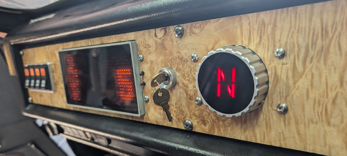
The Shift Knob
Click to play video
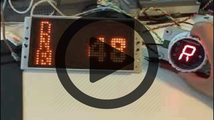
The motor controller has inputs for Drive, Neutral, and Reverse that need +12 Volts to turn the motor in that direction. Because all my lights are CAN-enabled, I will also need to somehow present the state of the ‘shift knob’ on the CAN bus. The most obvious solution to this problem is to simply read this state with an additional optoisolator circuit. I did not do this. I created something much cooler
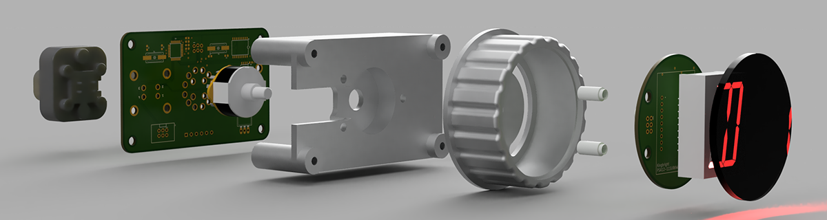
Above is the exploded view of my shift knob. It is a three-position rotary switch. Underneath the face of this knob is a 16-segment LED that shows ‘D’, ‘N’, or ‘R’, depending on the position of the switch. This rotary switch has four different center poles (it is effectively four separate 3-position switches), one pole of which is used by the motor controller, and a second read by an on-board microcontroller. This microcontroller sends the state of the switch over the CAN bus and also drives the 16-segment display.
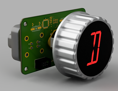
The really cool trick with this knob is the fact that the center indicator remains stationary as the knob turns. Turning the knob does not move the center indicator. It’s an effect that puts the ‘b’ in subtle, but is simply amazing when you notice it. It’s probably what I’m most proud of in this entire CAN conversion project.
A Replacement for the heater controls
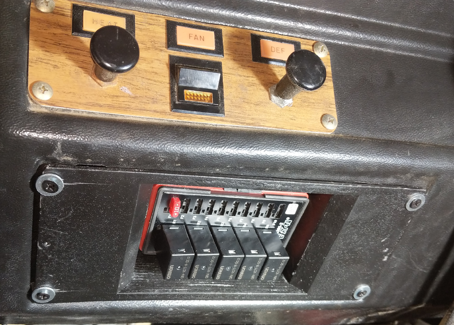
The stock Comutacar includes a ‘sub panel’ below the dashboard for what can generously be described as ‘environmental controls’. Actually, the HVAC system of the Citicar / Comutacar is hilarious, and deserves mention:
Motor cooling on the Citicar is accomplished by a twelve volt fan blowing cold air into the motor. This now-heated air is then recovered and sent into a manifold controlled by two pull knobs next to the dash. The heated air can be sent into the cabin, so everything smells like burning carbon brushes, or up to the dashboard, where it forms a rudimentary defroster. The only heat source in the entire system is the hot motor, there is no heat exchanger, and everything smells like blue smoke.
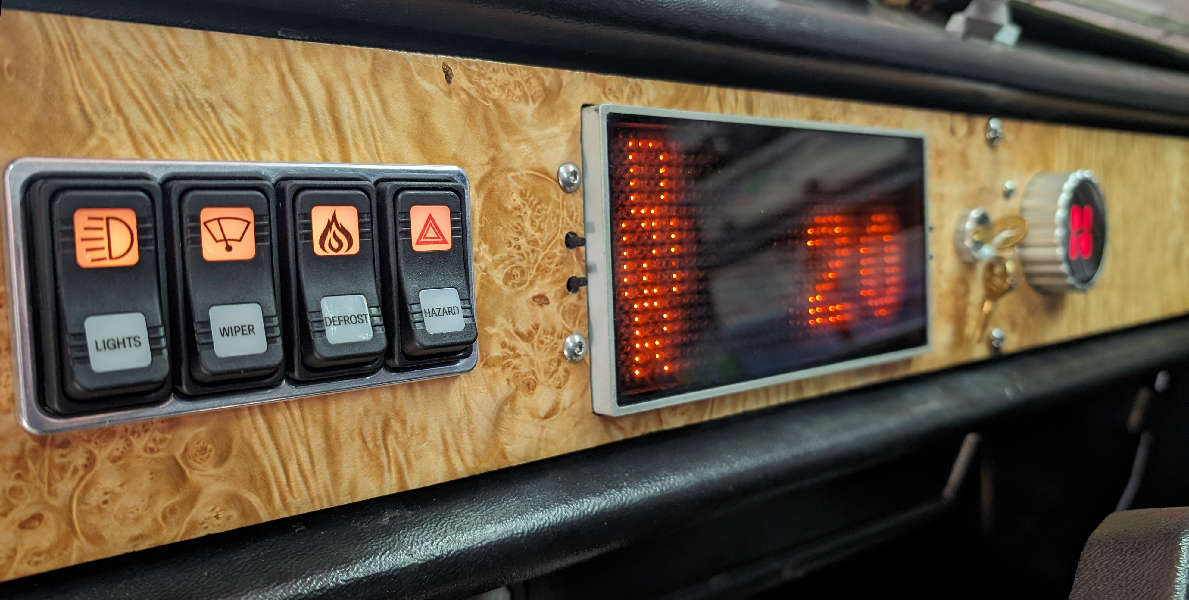
I will not be using the forced-air motor cooling and defrost system. The motor runs cool enough to not require cooling, and I am adapting a 12V / 150W Portable Car Heater to use as a defroster. This gives me space to add additional switches, or at least space for extra switches. I do not know what these switches will eventually do. One idea is to have a mode that changes the acceleration profile on the motor controller. Or a switch blinks the exterior lights randomly. Here’s a pic of the five-switch extension panel, along with the stock heater/manifold controls:
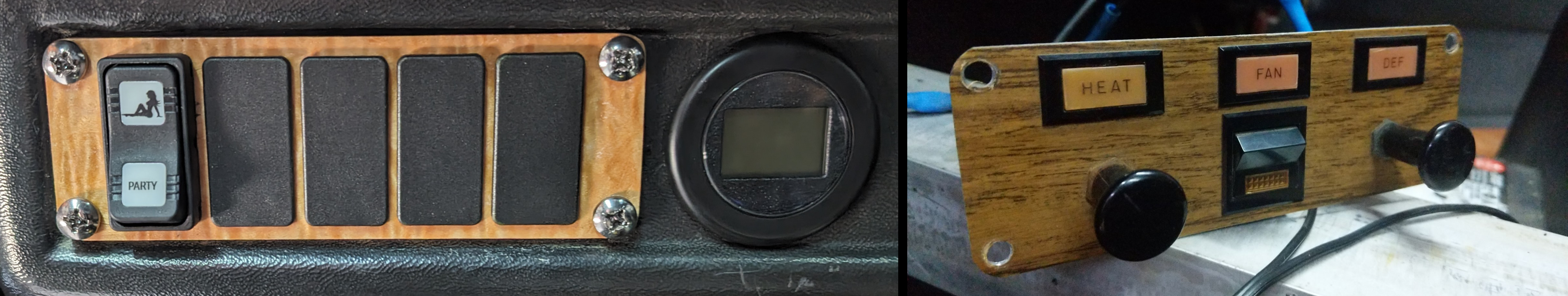
The additional round display is the Curtis 3140, a display for the motor controller itself. While this display is not technically necessary, it is hugely helpful for debugging and programming the motor controller. The rightmost switch position in the heater controls is taken up by two switches needed to program the motor controller – a ‘Menu’ button and a ‘Mode’ switch.
Integration with the rest of the car
One CAN bus will control the dashboard, lights, and the turn stalk indicator, but not everything. In an effort to reduce complexity on the CAN bus, I have broken it up into three parts: one for the battery, charger, and BMS, another for the motor controller, and the third for the dash and lights. The manual for the motor controller says I shouldn’t connect its CAN bus to the BMS and charger, so this will have to do. Here’s a pseudo-schematic of what I’m talking about:
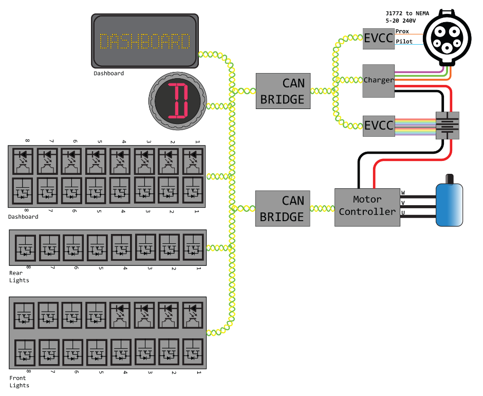
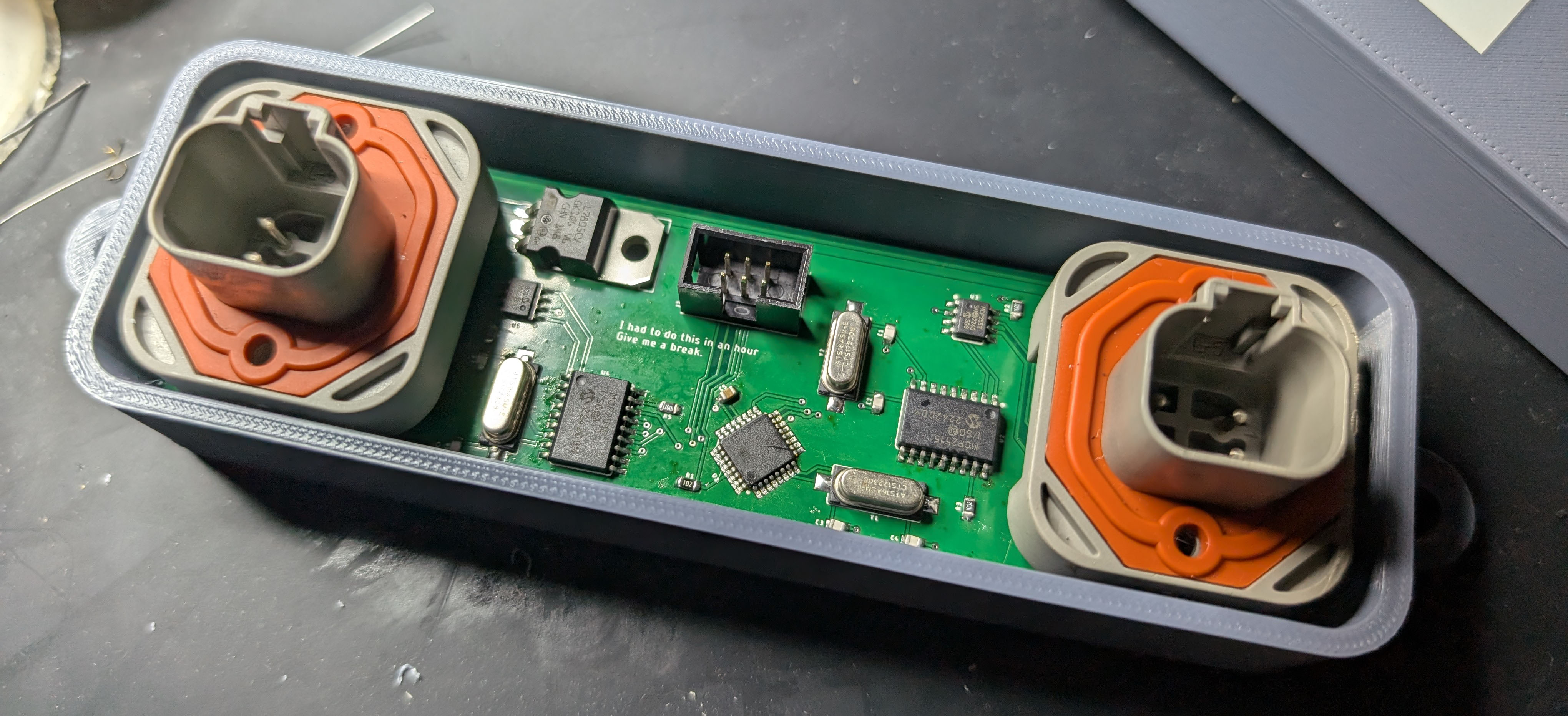
These CAN busses are tied together with a CAN bridge. Basically, it’s an Arduino with two CAN tranceivers. The microcontroller can read and write to each CAN bus it’s connected to. With a little bit of code, I can shuttle data across the bridge, even translating it to different data. Here’s the CAN bridge:
Putting it all together
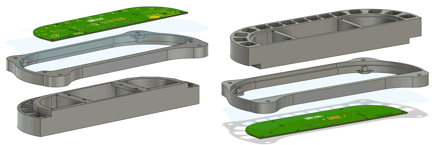
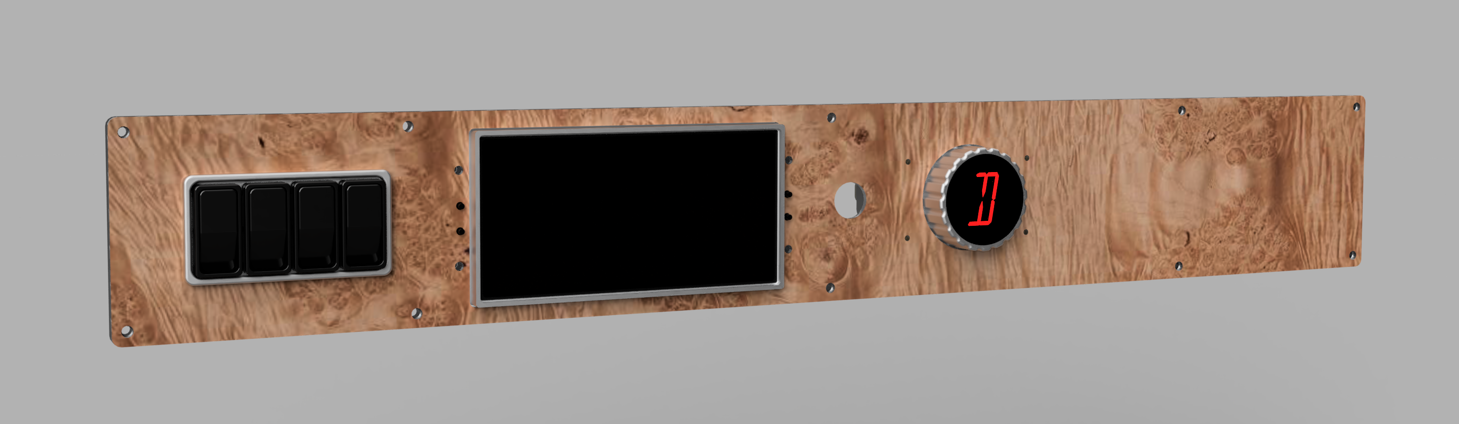
The stock Citicar dash is a single piece of 1/8” aluminum screwed onto the plastic dashboard with the help of clip nuts. These nuts are terrible to install, they fall off constantly, and they really don’t secure the dashboard to the car very tightly. For my dashboard, I’ve gone a different route, with a piece of 1/4” waterjet aluminum physically bonded to the plastic dash with a combination of glue and fiberglass.
To this 1/4” aluminum ‘backer plate’, I attach a 1/8” aluminum ‘front piece’ to which most of the components are mounted to. The ‘dashboard CAN MOSFET device’ is still bolted to the 1/4” backer plate, but everything else - the shift knob, display, ignition switch, and aluminum switch bezel - are attached to the 1/8” aluminum front piece.
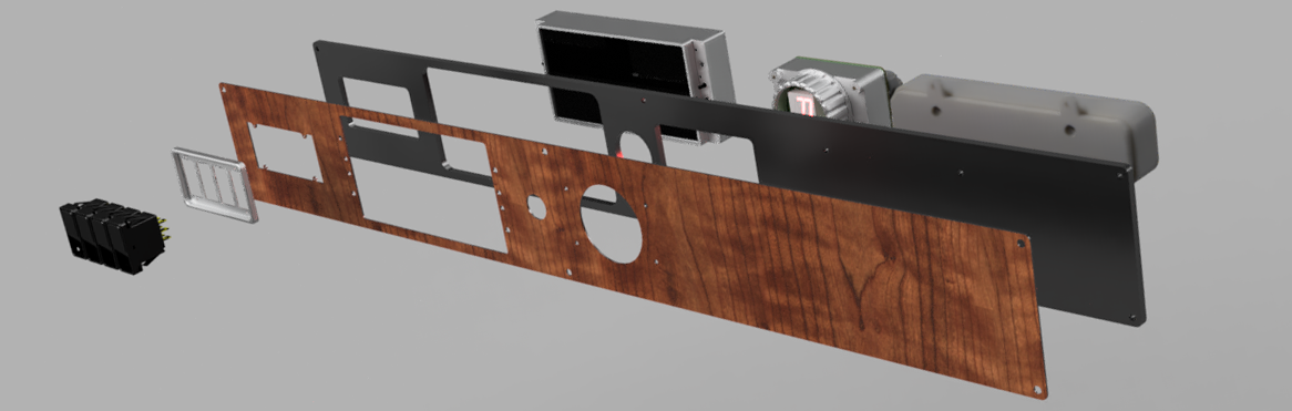
To give the front piece a little more class, I bought a long piece of maple burl veneer and attached that with contact cement. It looks amazing. Here’s the render of the final product, and a crude assembly diagram:
Part 4, Body repair, bumpers and cosmetic issues
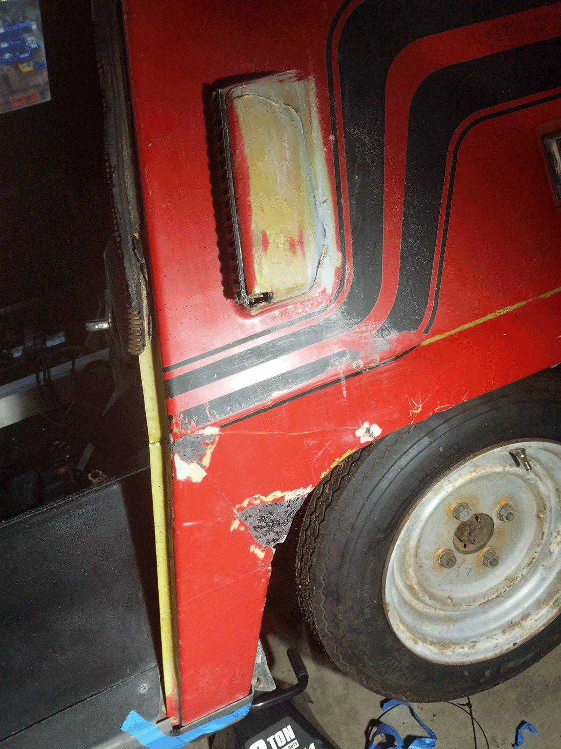
When I acquired the car, the body was by no means perfect. No Citicar is; the entire chassis is an aluminum tube frame clad with exactly six ABS plastic panels: four quarter panels, a back panel, and a huge plastic panel for the front and top of the car. All Citicars have at least one large crack next to the windshield, caused by decades of expansion and contraction. Mine has several more cracks, the most notable on the back top corners, with several other major gashes around the car. There are also missing pieces of panels – on the driver’s rear quarter panel, most of the bottom is missing, and the ‘vent’ was completely cracked off. The remaining pieces were saved by the previous owner, and I think I’ve figured out the best way to repair them.
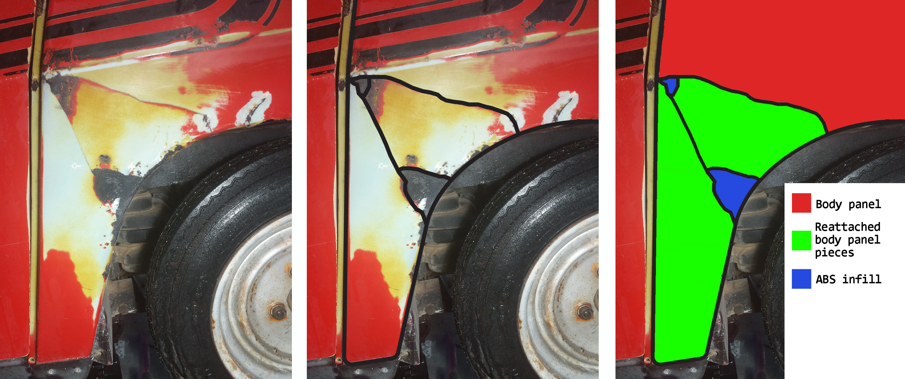
Since the body panels are ABS plastic, conventional wisdom says acetone is the best solvent to join panels back together. Chemistry says something else, and the ingredients of most ABS ‘glue’ are 10 parts MEK with one part acetone. The thinking, I think, is the acetone bonds the parts quickly, while the much stronger MEK takes a few days to fully cure. I’m looking for strength, so that’s what I went with. To fill any holes in the body, I’ve come up with a technique that uses plastic welding (a soldering iron and ABS 3D printer filament) with this MEK/acetone solvent. After slightly melting some filament to the body panel, I apply the solvent and let it cure. Sand a few days later and repeat. It is not fast, but there really are no other solutions for fixing a huge plastic panel like this. While the repaired driver’s quarterpanel isn’t much to look at now, the entire car will eventually be sanded and painted.
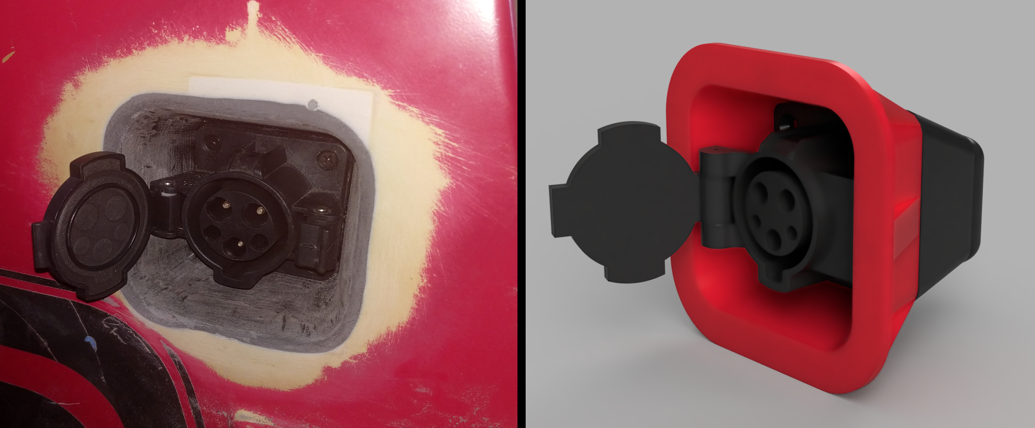
Essentially, I created a plastic ‘bucket’ in Fusion360 in which a J1772 port can be mounted. This bucket has a large flange on its rim, which allowed me to attach it to the body panel with Devcon Plastic Welder. With the bucket glued to the body panel I then routed the body panel with a bottom bearing edge trim router bit and sanded a fillet between the body panel and the bucket. The result is a J1772 port flush-mounted to the car’s body. A 3D printed cover on the back includes threaded inserts and holds the J1772 port in place. This cover also hides and redirects the power cables to a location under the passenger seat, where the charger will reside. With paint, this will look stock, or at least what the car would have looked like, had J1772 ports been invented thirty years earlier.
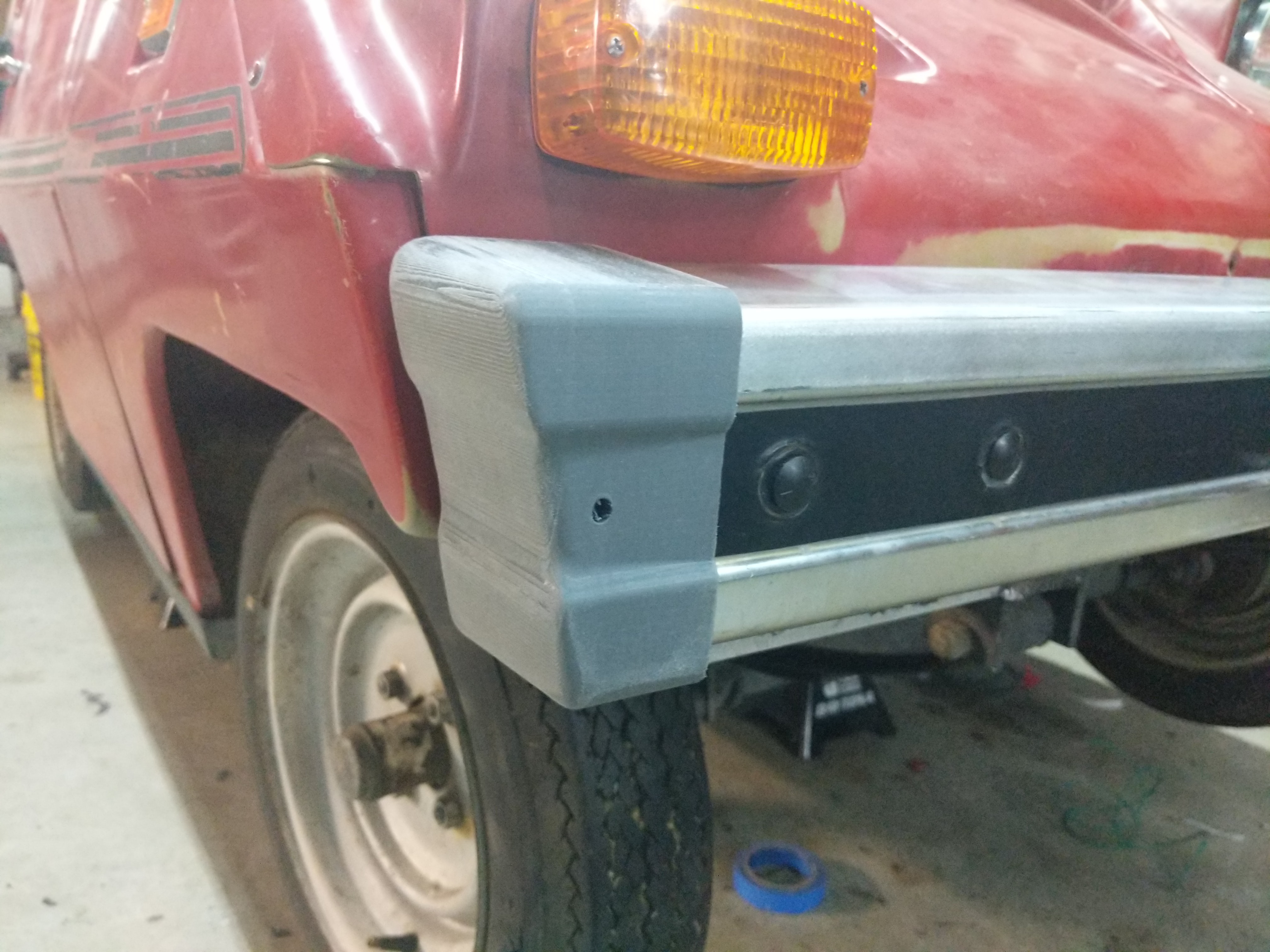
Oh the bumpers
While the Citicar had small bumpers made of a piece of wood wrapped in closed-cell foam, the later Comuta-Cars had large protruding bumpers on the front and rear. Despite conventional wisdom, these were not 1970s safety regulation bumpers, at least not the way you would think. Comutacar models added several aluminum beams underneath the seat for rigity and ostensibly impact resistance (lol), and this took up valuable battery space. Instead of putting the batteries under the seat, they had to go somewhere else, and that place was a box under extended bumpers. I’m using fewer batteries, and have wired up all of the high-power electronics under the seat, so these extended bumper battery boxes need to go. They’re ugly. Also the closed-cell foam has degraded over the past 40 years and now bare wood is showing.
There are several references to replacing Citicar bumpers with the bumper from a Mk1 VW Rabbit, and even some references to replacing the bumper on a Comuta-car with a bumper from a Dodge Omni / Plymouth Horizon. I’m going with VW Rabbit bumpers. Both the bumpers need to be from the rear of a Rabbit – the front bumper has a slight curve to it, whereas the rear bumper will lay flat against the body.
The ugly front bumper was removed, and is attached to the frame of the car with a large 4”x3” aluminum angle, 0.25” thick. The original mounting for the VW bumper is with a pair of carriage bolts on each end - this will mount the bumper to the aluminum angle. This aluminum angle is mounted to the car using the same holes as the battery box. Unfortunately, mounting the aluminum angle using the same holes as the old bumper will not work – there simply isn’t enough space to turn a wrench. Mounting the bumper in this fashion will be much easier to disassemble in the future while allowing a cut-down battery box to be used, giving the car extended range.
While the bumper and aluminum bracket work wonderfully, the stock end caps for the VW bumper do not. They stick out down the length of the car, and they’re far too massive. I modeled new bumper end caps in Fusion360 and printed them out in PLA. They will eventually be painted in PlastiDip spray, but even as bare gray PLA they still look great.
Part 5, Tires and Brakes, Brushes and Diffs
The car needed new tires, and there are several options. Citi/Comutacars came with either 480x12, 125/80R12, or 135/80R13 tires, with the tires on mine being 480x12. I found a 20-year old site (that’s a link to the Internet Archive, you’ll thank me later) detailing the possible replacements, and decided to go with the stock solution – 480x12 tires meant for boat and motorcycle trailers for $150 on Amazon. Yes, the plan is to eventually put some nice radials on the car, possibly even whitewalls, but for now cheap trailer tires will do. Get some valve stems, buy the Ryobi tire pump, and things should go easily. I’ll also need to clean and paint the rims and let them sit for a week or so.
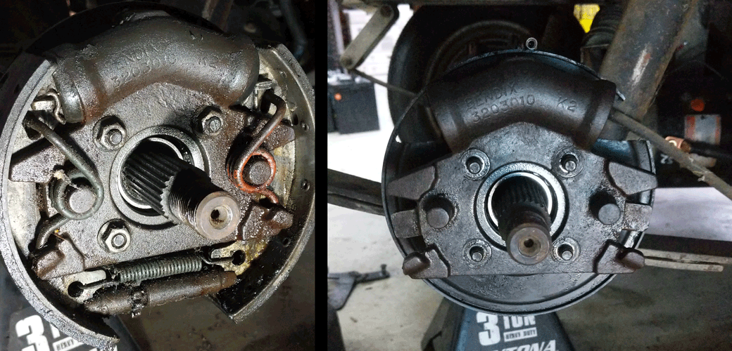
Brakes are another matter. While the car nominally came with tires that hold air, it did not come with brakes that work. It did, however, come with a brake drum in the big box ‘o parts, and after pulling off the front passenger wheel, I figured out why: the car did not come with an extra brake drum. When I bought the car, there was no drum on the front passenger brake, and the wheel had three random washers on the studs. This is sketch as fuck.
After draining and bleeding the brake lines, ‘squishy’ brakes persisted. This problem was eventually identified as a leaky seals on the brake cylinders. The brake cylinder / spider assembly is a Bendix 3203010, and the torque spider repair kit (BK33-190, EZ 13959-G1) runs about $80. That’s for one wheel, and I might as well replace the seals and boots on the other rear wheel while I’m at it. The bleeder screws were replaced (NAPA UP 6446), along with one torque spider assembly (OEM Part number CU 824829, 886875) that had a stripped bleeder screw thread. I’d like to emphasize the brakes are almost entirely rebuilt, with the exception of the master cylinder. The master cylinder works, though, so I think we’re good.
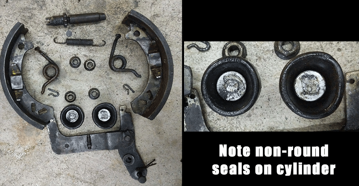
The below pic is the disassembled parts of the rear brake drum. Note the pic of the seals – one is very oblong, this was the seal that was leaking.
With new seals on the rear wheels, squishy brakes persisted. On further inspection, the seal on the front passenger brake was leaking. Fixing this was a bit trickier; either through decades of decay or my misapplication of torque, the threads for the bleeder valve were partially stripped. I bought a new torque spider for the front passenger brake, and with that bolted on the brakes worked like new. While I’m not impressed with the ‘one man’ vacuum brake bleeder I have (the girlfriend had to stomp on the brakes while I went around bleeding everything), the brakes now work. In total, the brakes on the car took about a month, with most of that waiting for various tools and parts to arrive. That’s not a problem – now my garage has a few more tools, and I know how to build more brake lines.
Part 7, Body off restoration, and The Necessity of Graphics
As noted above, the car came to me with a few broken panels. The Driver’s rear quarterpanel was the worst, with a broken vent and a few other pieces broken off. These broken parts came with the car, and I was able to reattach and reinforce them. No problem, really.
However, the car also had many cracks in the body panels. There are cracks along the windshield, just like every other citicar on the planet, there are cracks on the roof, and the top driver’s side corner of the rear panel is very broken. All of these cracks can not be easily fixed with the body panels on the car. Additionally, the ‘foam’ (or whatever it is) around the aluminum space frame has degraded into sticky dust, and I’d like to get that off. And I want to re-paint this thing. The solution to all these problems can be solved by pulling the body panels off the car. I have never seen this done and the plastic is extremely brittle.
In preparation for this, I made replicas of the decals on the citicar. These will eventually be recreated with a vinyl cutter and transfer paper:

While the graphics may seem like a small part of the project, they are necessary. Without graphics, the car looks like an automotive stealth bomber dreamed up in a deranged Wonka-esque car factory. With graphics, everything pops. To illustrate this point, I’ve printed out a 3d model of a comutacar, cut the graphics out of vinyl. The difference is stark:
A Battery Upgraded From Trash
My job has a lot of random trash sitting around, and one interesting piece was an LG RESU home battery solution. This is a powerwall, a giant battery for solar and backup installations. Work needed to get rid of it, and I’m building an electric car. This is at least 16kWh, possibly 20kWh, of batteries for free. Of course I need to hoard it in my garage.
This powerwall came with no documentation, and not even a model number stamped on the case. It was an LG prototype as far as I could tell, meant for ‘integration partners’ or some other B2B nonsense. Either way, it’s completely undocumented so I really don’t know what I have here.
This unit is built of five modules stacked together, with the sixth plastic box on top housing the electronics. The electronics were quickly scrapped because I only want bare cells. Each module is a 14s pack, meaning 58.8V fully charged. Wired in parallel, this would be an acceptable battery pack for my car with minimal reprogramming using the same BMS I’ll use for Chrysler Pacifica packs.
At the very least, this is an option to greatly extend the range of my car. For now, I’ll be using a single Chrysler Pacifica pack to test drive the car, and will decide on further upgrades down the road.
Paint and The Necessity of Graphics
Pop Rivets
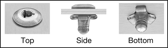
The bodywork is made of six monolithic pieces of ABS plastic: the back, two front quarterpanels, two rear quarterpanels, and one gigantic piece forming the front and roof of the car. These are bonded together first with a bit of glue and secondly with pop rivets. Normal pop rivets won’t work, because the ABS is far too brittle – in fact, most of the existing major cracks in the body are right where the rivets are.
The manufacturers’ solution to this problem was a special type of pop rivet that is softer and expands more than a standard pop rivet. Original, new old stock Citicar rivets are available, but they cost about $0.50 USD each. That’s too much. McMaster-Carr sells these rivets for about $0.16 USD each. Here’s McMaster’s diagram of what they look like installed:
Door and Window Seals
After acquiring the car, I noticed the door seals had completely rotted away. Inexplicably, the window seals for the back glass were completely intact, and in great condition. From a few forums, I found these were the same seal but could not find a reference to the part number of the seal that had not linkrotted away. The only solution to this problem is to take measurements of the rear window seal and find something similar for the door seals.
A reasonable facsimile of the original door seals are available in the UK
Parts and replacements
| Part | Replacement | Cost |
|---|---|---|
| Rear glass gas strut | Napa / Balkamp BK 8195581 | $28.99 |
| Shock Absorber | Monroe #94037 / NAPA PNS 94037 | $30.69 |
| Ignition Switch | Cole Hersee 9577-BX | $15.99 |
| Rear Hazard Light | Peterson Manufacturing V126R Red Clearance Light | $14.23 |
| Windshield Wiper Blade | Anco 51-20 / NAPA part number 602050 | $14.37 |
| Turn Signal Stalk | 77-80 Triumph Spitfire / 30968X / LUCAS SQB195 | $36.75 |
| Fuse Panel | Eaton / Bussmann 15305-2-2-4 | $45.46 |
| Direction Contactor | Albright SW202-142 (ebay) | $99.99 |
| Replacement Controller | Curtis 1209B-6402 | $219.22 |
| Motor Brushes | Carbon Brush 0.5” x 0.625” x 1.437” item 10-506221 | $67.60 |
| Brake seal parts | BK33-190 Torque Spider Repair Kit | $77.73 |
| Motor Mount Seal | Federal Mogul 352352 Steering Gear Pitman Shaft Seal | $10 |