An Isolated Thermocouple Reader
The problem
As a sort of test and measurement engineer at my job, we have to take temperature measurements on live electrical circuits. A thermocouple is great for this – you can simply embed the tip of a thermocouple wire inside a block of copper and you’ll get its temperature even if there’s 500 Amps going through it.
The hardware for this is expensive. The National Instruments 9212 is an 8-channel electrically isolated thermocouple input module for the NI family of DAQ units. This module costs $1600, and that doesn’t even consider the ‘base station’ each of these modules needs. If you want to read electrically isolated thermocouple inputs, expect to spend at least $250 per channel.
I can do this for about $15 per channel.
One chip does all the work
Thermocouples are just two bits of wire made of dissimilar metals that produce a voltage proportional to temperature. At full scale – the minimum and maximum temperatures published in thermocouple lookup tables – the voltages are fairly large and on the order of -10mV to about +50mV. That’s 1/10000th to 1/50000ths of a Volt. To get sub 1°C resolution I will need to measure microvolts, or millionths of a volt. With a range of +/- 50mV for the DAC, that means I need an effective resolution of at least 16 bits.
These inputs also need to be isolated. There is a chip that does this, the Texas Instruments AMC3336 and related chips like the AMC3306M05 (+/- 50mV), and AMC3305M25 (+/- 250mV). These chips are isolated delta-sigma (ΔΣ) DACs. They all operate with a single power supply of 3.3V, and they will read the microvolt voltages needed for thermocouple measurement.
The specs for these chips is great, especially on the AMC3306M05. single 3.3V supply will allow me to read a single thermocouple input, +/- 50mV, at about 16 bits of resolution. It has 1200V of isolation. The only problem is that it’s a ΔΣ DAC, so I need to figure out how to read that.
Operation and reading of a ΔΣ DAC
A ΔΣ DAC is simple to describe – feed it a square wave, and it will give you another square wave at half the frequency, the duty cycle of which is proportional to the voltage on the input. Here’s what it looks like on an oscilloscope, clock input on top, signal on bottom:

The ideal tool for this is the RP2040, also known as the Raspberry Pi microcontroller. The RP2040 has a PIO module that can toggle and read GPIOs very fast. Think of it as the microcontroller version of the BeagleBone PRU.
Each of the two PIOs on the RP2040 has four State Machines (SM), a “sub-processor”, with a handful of registers (four, actually, x, y, and an input and output shift register) and runs a handful of instructions (read, write, shift in, jump, and decrement). The input and and output shift registers are 32 bits wide, meaning if you want to read a ΔΣ DAC, you can only read 32 points before shifting that data out to the main processor via DMA.
To use these PIOs with the ACM3306, one SM needs to generate a clock. Another SM needs to wait for an IRQ from the clock generator PIO, then read a pin and shove it into the Input Shift Register. The code for each is listed below
Clock Gen PIO code
.program clock_gen
    set pindirs, 1       ; Set pin direction to output
.wrap_target
    set pins, 1          ; Set pin high
    nop                  ; Delay for low state
    set pins, 0          ; Set pin low
    irq nowait 0         ; Set IRQ 0 for the other SM.
                         ; This is a non-blocking IRQ, it
                         ; only sets a flag to be read by
                         ; other state machines
    set pins, 1          ; Set pin high
    nop                  ; Only want one IRQ
    set pins, 0          ; Set pin low
    nop                  ; Delay for low state
.wrap
ACM Read PIO code
.program sample_counter
    set pindirs, 0          ; Set pin direction to input
    set x, 31               ; Initialize x for 32 bits
.wrap_target
do_capture:
    wait 1 irq 0            ; Wait for IRQ 0 (triggered by clock_gen)
    in pins, 1              ; Read 1 bit and shift into ISR
    jmp x-- do_capture      ; Loop until x is 0
    push block              ; Push 32 bits from ISR to RX FIFO
    set x, 31               ; Reload x for the next 32-bit capture
.wrap
A graphic representation of what’s happening in this code is shown below. This code relies on setting an IRQ on the clock_gen PIO code, and reading that IRQ in the sample_counter PIO code.
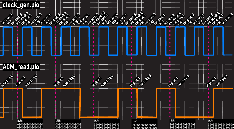
This code collects 32 bits into the Input Shift Register of the PIO, and shoves that over to the main CPU when it’s full. using _builtin_popcount() I can count the number of high bits and eventually get the proportion of high bits to total bits in the ΔΣ signal.
This works for one channel, but because the RP2040 only has eight total State Machines, I cannot read eight channels while generating the clock signal. The RP2350 with twelve total SMs is a much better fit. I’ll use that for the production version of this.
The Analog Front End
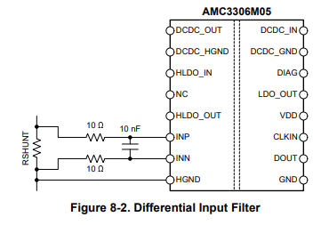
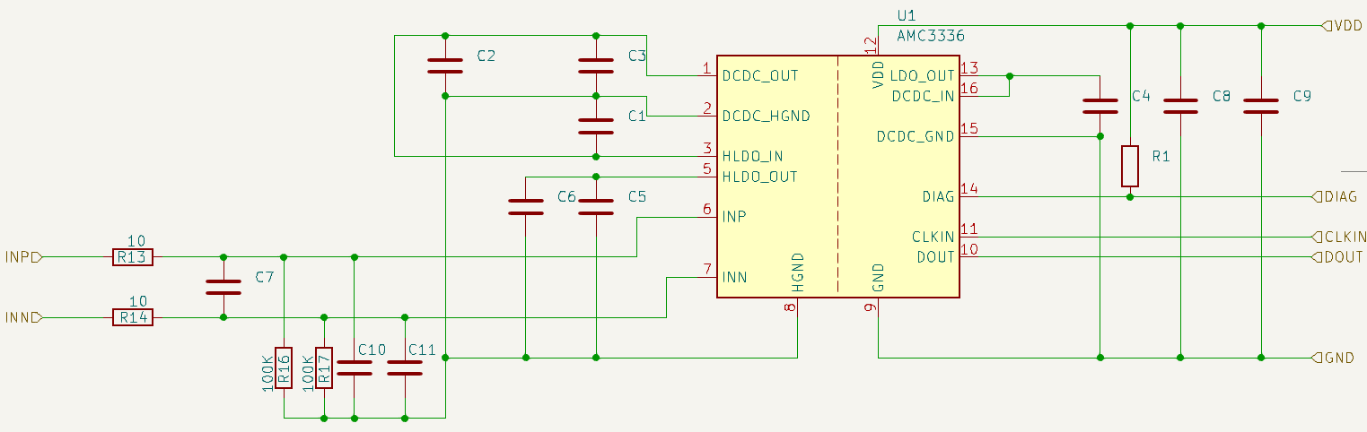
The standard input configuration for the AMC3306 is just two 10Ω resistors and a 10nF capacitor for an RC input filter. Very simple.
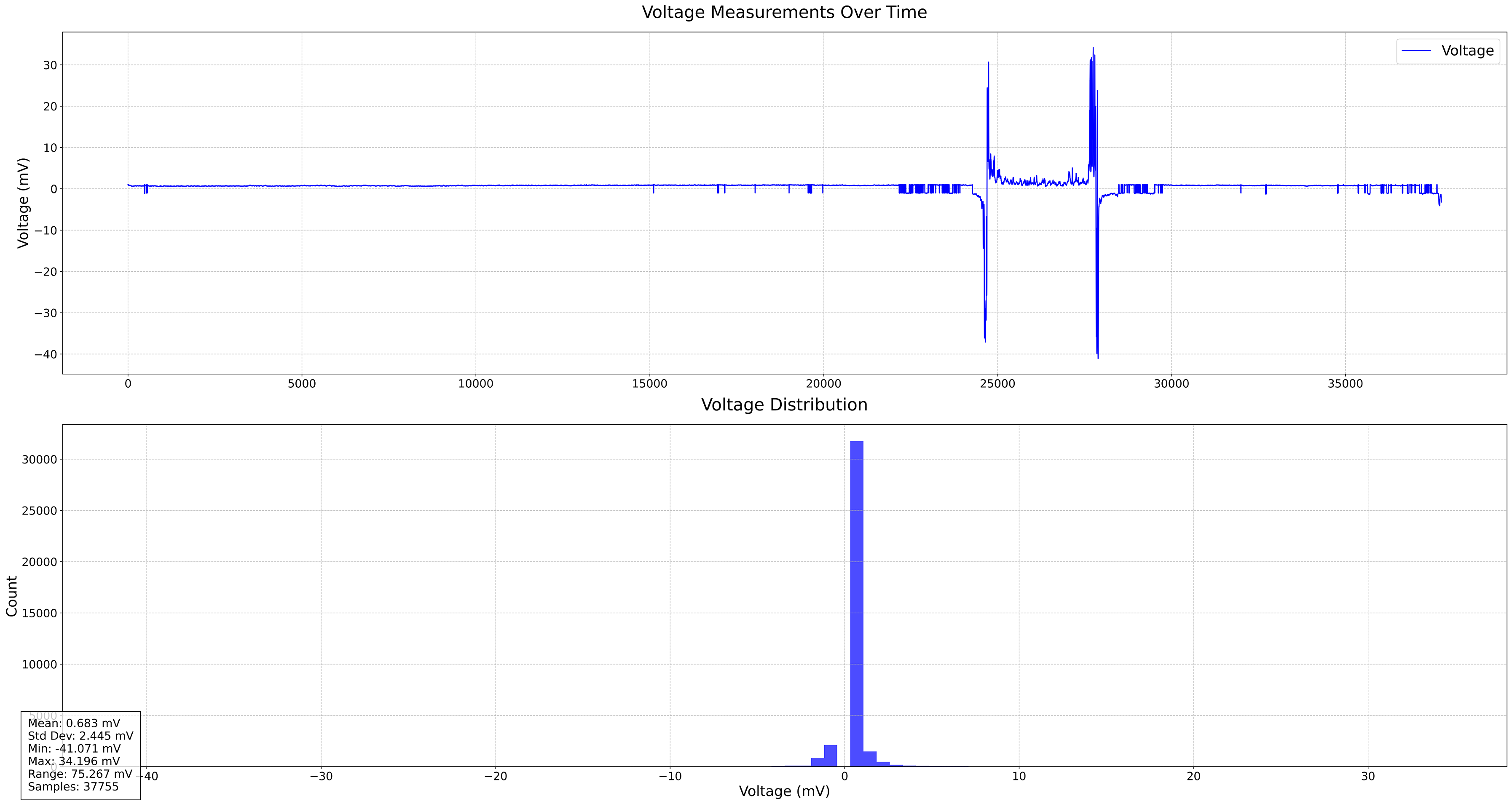
However, the data I was getting from this input was not very good. I tested the input on a T-type thermocouple at room temperature for about 9 hours, resulting in a range of 75mV; obviously a measurement error, but absurd and worthy of a redesign. The mean for that data was 0.683mV, with a standard deviation of 2.445mV. This is far too large of a range – if one measurement is off by a standard deviation, it means a temperature difference of nearly 50°C. Here’s the data plotted:
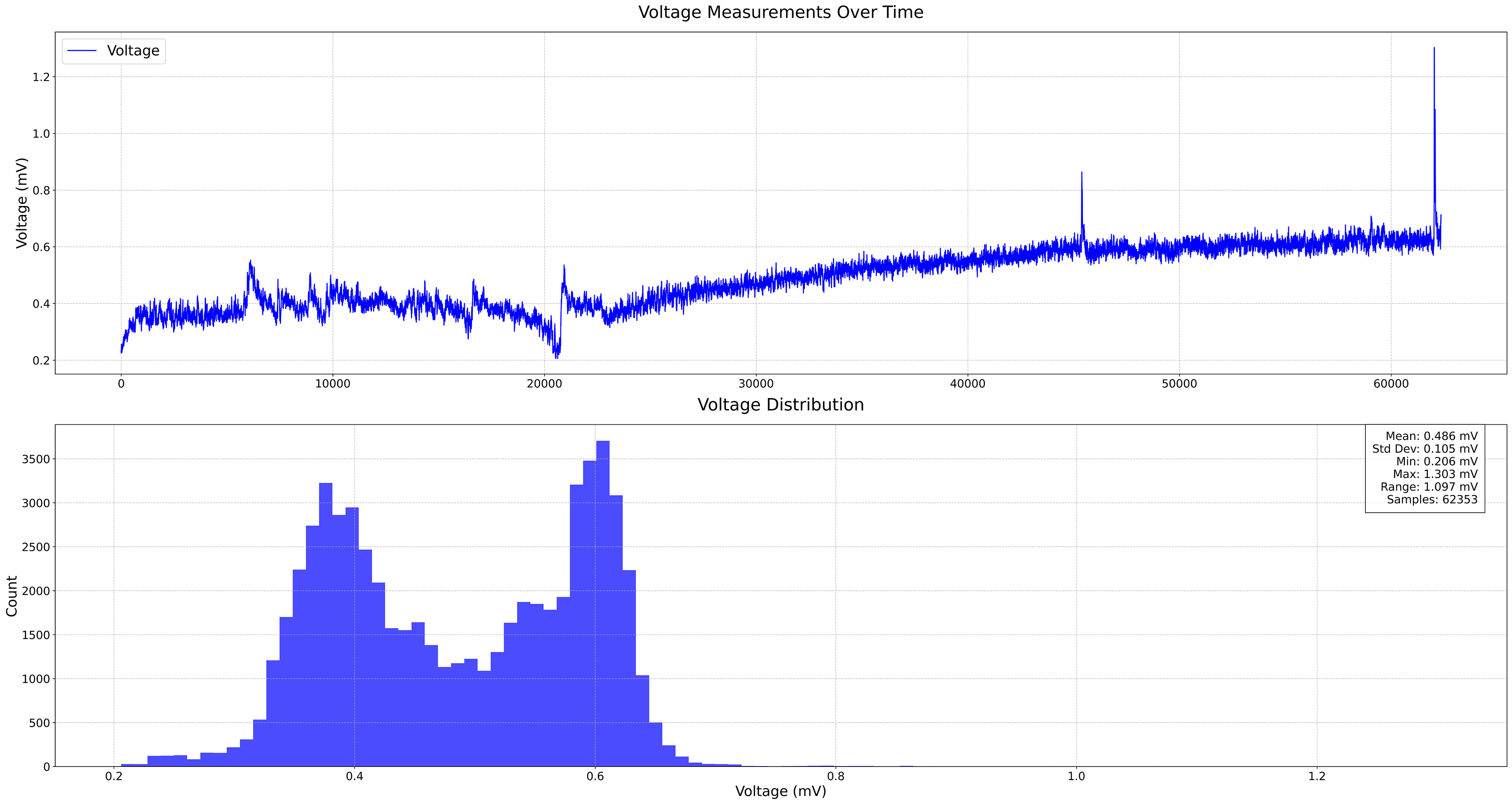
The standard input configuration from the datasheet wasn’t delivering the performance I needed, so I made two key modifications. First, I added 100kΩ resistors from each input to ground to provide a defined DC bias point. Without these, the inputs were essentially floating except for the internal chip biasing. Second, I added capacitors in parallel with these bias resistors to provide additional high-frequency noise filtering. This was possible because the AMC3306’s isolation barrier means we don’t need to rely on perfect common-mode rejection - the isolation takes care of rejecting large common-mode voltages for us. The combination of stable biasing and additional filtering improved the standard deviation of my measurements by more than an order of magnitude, from 2.445mV to 0.105mV, making the device actually usable for thermocouple measurements. Here’s the revised front end:
The data from the new analog front end is impressive. The standard deviation is now 0.105mV, an order of magnitude better than the input suggested from the datasheet. Now the standard deviation to temperature error is within a single degree, making this a usable data acquisition device.
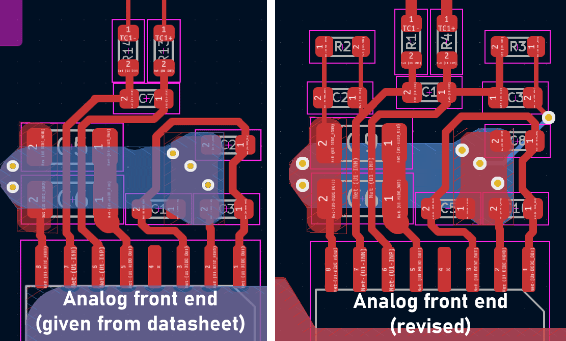
I’m going to put the comparison of the board layouts between versions of the input here, just because I’m sure I’ll be referencing it later:
Sync3 filters
The PIO code gives me a bitstream for each output of an ACM3306 chip, but I still need to turn that into a voltage which will eventually be converted into a temperature.
To process this data, I’m using a Sync3 filter that works like this:
- Integration Stage: Each stage of the Sync3 filter sums the incoming signal over a specified period, more specifically a specified number of samples. I believe it’s 4096 DMA transfers, so 131,072 individual samples (4098*32).
- Comb Filter: This removes the noise and harmonics of the signal.
- Decimation: After filtering, the Sync3 filter applies decimation or keeping only every nth sample. I believe I’m only keeping every 16th sample. This is the easiest place to ‘tune’ the filter, giving me the required signal resolution with the lowest computational cost.
- Running Average: Putting a running average on the output of the filter gets rid of transient noise and outliers.
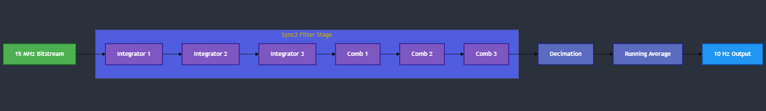
The filter also includes a running average to further smooth the output. The result is remarkably clean voltage readings. I’m getting microvolt resolution and sample rates around 10Hz.
Somehow it’s 120Mbps
Because the microcontroller I’m using has a fantastic DMA system, I’m using the RP2040 to automatically transfer blocks of data from the PIO’s RX FIFO to memory without CPU intervention. This greatly reduces the processing burden on the main CPU, enabling it to focus on tasks such as additional signal processing.
As a quick aside, reading one channel of ACM DAC data is processing about 15 Megabits per second. Eight channels is 120Mbps. That’s processing data faster than late 90s Ethernet on a chip that costs $4. That’s absurd.
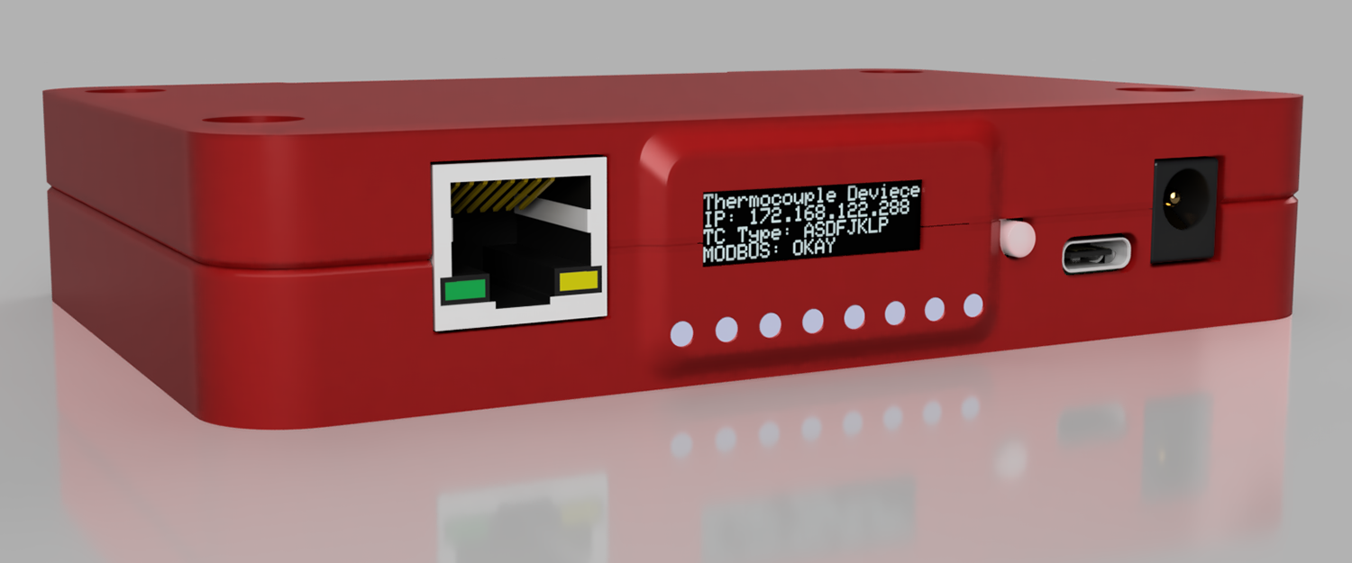
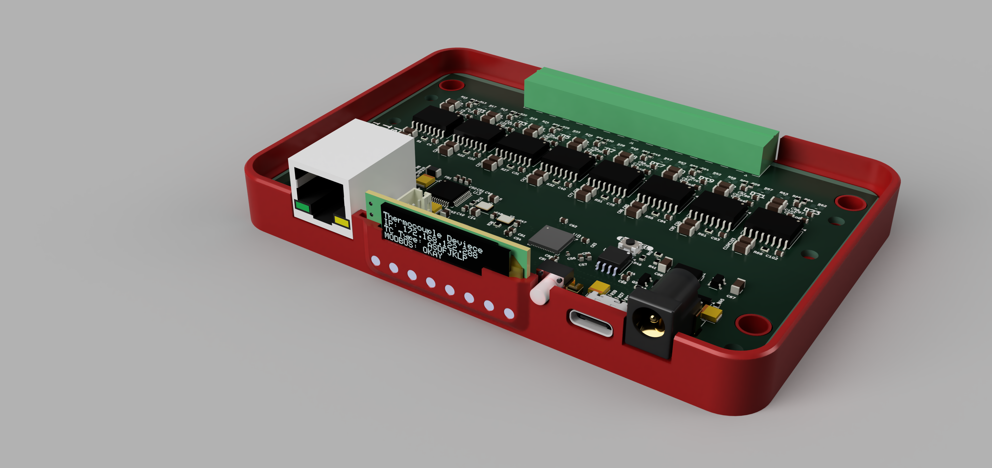
Device Hardware
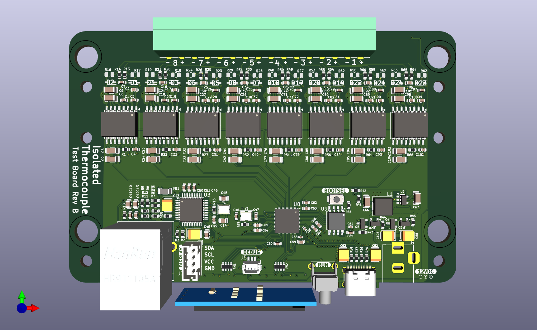
For this to be a useful industrial DAQ, it needs to have inputs and outputs. For this, I added a W5500 Ethernet controller. USB-C is the future, but I don’t need USB3. I wired up a USB-C port as a USB 2.0 interface, which is sufficient. Power is provided either through the USB-C port or a barrel jack while four transistors form a power OR circuit, allowing this device to be powered by either the barrel jack or USB port.
One thing I’ve noticed on industrial hardware is the complete lack of a user interface. I’ve used Ethernet DAQs where the only way to tell what IP address a device is set to is to use nmap after plugging it in. This device has a small OLED display that shows you its own IP address. I expect this to save at least a man-week of work every year. There are also side-mounted LEDs below this display and light pipes through the case. Even I question the utility of these LEDs but they look great and were cheap to implement.
Connectivity is mostly through Modbus over Ethernet, although streaming over serial is also supported. This is in line with most of the other data acquisition tooling at my job.
A thermocouple reader also needs cold-junction compensation, or a temperature measurement of the interior of the device. This is accomplished by an LMT01 temperature sensor placed underneath the header for the thermocouples. This is read by another bit of PIO code on the microcontroller, freeing up a little bit more processing power.