
Video Intro
Project Overview
OrthoRoute is a GPU-accelerated PCB autorouter, designed for parallel routing of massive circuit boards. Unlike most autorouters such as Altium Situs, FreeRouting, and a dozen EE-focused B2B SaaS startups, OrthoRoute uses GPUs for parallelizing the task of connecting pads with traces.
The main focus of OrthoRoute is a unique routing technique borrowed from FPGA fabric routers. Instead of drawing individual traces, it first creates a 3-dimensional lattice of traces on multiple layers. Algorithms borrowed from the FPGA and VLSI world are used to connect individual pads. Unlike push-and-shove routers, OrthoRoute pre-lays a Manhattan lattice and uses a negotiated-congestion router (PathFinder) to produce valid connections for all nets.
OrthoRoute is designed as a KiCad plugin, and heavily leverages the new KiCad IPC API and kicad-python bindings for the IPC API.
Key Features:
- It’s a KiCad Plugin: Just download and install with the Plugin Manager
- Real-time Visualization: Interactive 2D board view with zoom, pan, and layer controls
- Professional Interface: Clean PyQt6-based interface with KiCad color themes
- GPU-Accelerated Routing: Routing algorithms in CUDA
- Multi-algorithm routing: Some boards are better suited to different algorithms
- Manhattan Routing: A grid of traces, vertical on one layer, horizontal on the other
- Lee’s Algorithm: Also, a traditional push-and-shove router (experimental)
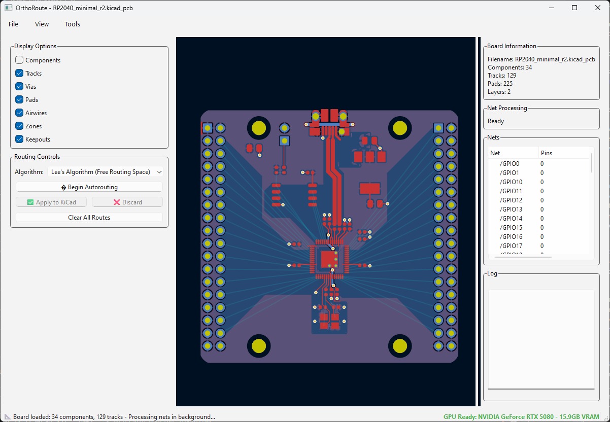
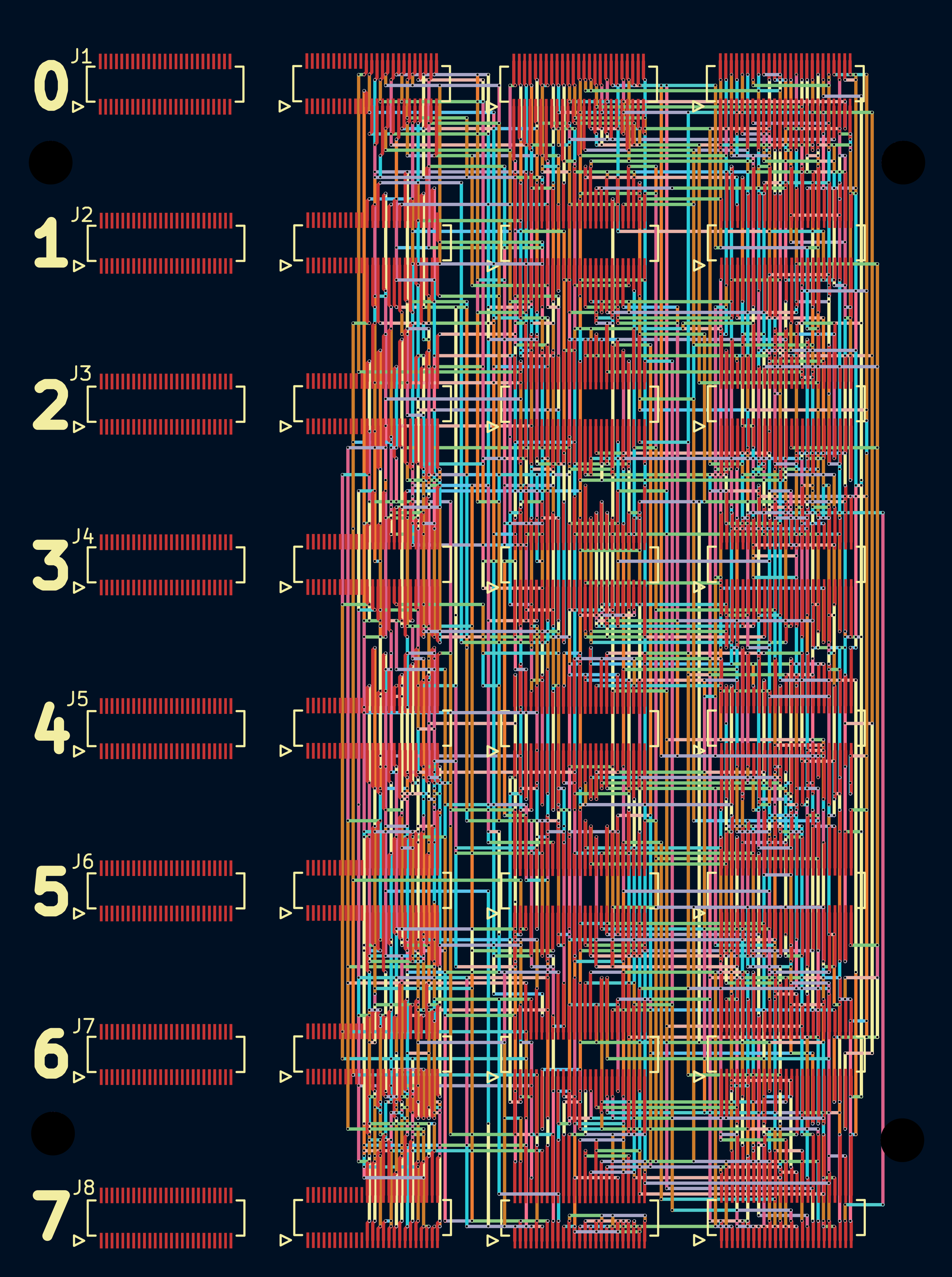
Screenshots
Why A GPU-Accelerated Autorouter Is Dumb
Before digging into the development of two separate autorouting engines, I’d first like to explain why building an autorouter for a GPU is a dumb idea. I’m going to explain this first because this specific insight plagued the development of both routing engines.
Autorouters are an inherently unparallizable problem. Instead of mapping an entire (blank) PCB into a GPU’s memory and drawing traces around obstacles, an autorouter is about finding a path under constraints that are always changing. If you have three nets, route(A→B), route(C→D), and route(E→F), you start out by routing the direct path (A→B). But (C→D) can’t take the direct path between those points, because it’s blocked by (A→B). Now (E→F) is blocked by both previous routes, so it takes a worse path.
It's _like_ the traveling salesman problem, but all the salesmen can't take the same road. Also there are thousands of salesmen. Should net (A→B) be higher priority than (C→D)? GPUs hate branching logic. You can't route (C→D) until you've routed (A→B), so that embarrassingly parallel problem is actually pretty small. Now deal with Design Rules. If you don't want a trace to intersect another trace of a different net, you apply the design rules. But this changes when you go to the next net! You're constantly redefining whatever area you can route in because of Design Rules, which kills any GPU efficiency.
But all is not lost. There’s exactly one part of autorouting that’s actually parallel, and a useful case to deploy a GPU. Lee’s Wavefront expansion. You route your traces on a fine-pitch grid, and propagate a ‘wave’ through the grid. Each cell in the wave can be processed independently. Shortest path wins, put your trace there. That’s what I’m using the GPU for, and the CPU for everything else. Yeah, it’s faster, but it’s not great. Never trust the autorouter, but at least this one is fast.
Bug-finding and Path-finding.
After using the IPC API to extract the board, I had everything. Drills, pads, and copper pours. The next step was to implement path finding. This is the process of selecting an airwire, and finding a path between its beginning and end. This is what autorouters do, so I’m using standard algorithms like Wavefront expansion, and a few other things I picked up from a VLSI textbook. All I needed to do was convert that list of pads and traces and keepouts to a map of where the autorouter could draw traces.
The key insight here, and I think this is pretty damn smart, is that a copper ground plane is the map of where traces can go. If I create a board with a few parts on it and put down a ground plane, that ground plane defines where the autorouter can draw traces.
While the kicad-python library has functions that will return the polygon of a copper pour, I can’t use that. Not all boards will have a copper pour. What I really need to do is reverse engineer the process of making these copper pours myself. I need a way to extract the pads, traces, and keepouts and applying DRC constraints to them.
That’s exactly what I did. First I learned how to extract the copper pour from a board, giving me a 5000-point polygon of copper with holes representing pads, traces, and clearances. Then, I reverse engineered this to create a ‘virtual’ copper pour – one that could be generated even if the KiCad board file doesn’t have a copper pour. By comparing this ‘virtual’ copper pour to the ground truth of the copper pour polygon extracted from the board, I could validate that my ‘virtual’ copper pour was correct. This gives me an exact map of where the autorouter can lay down copper.
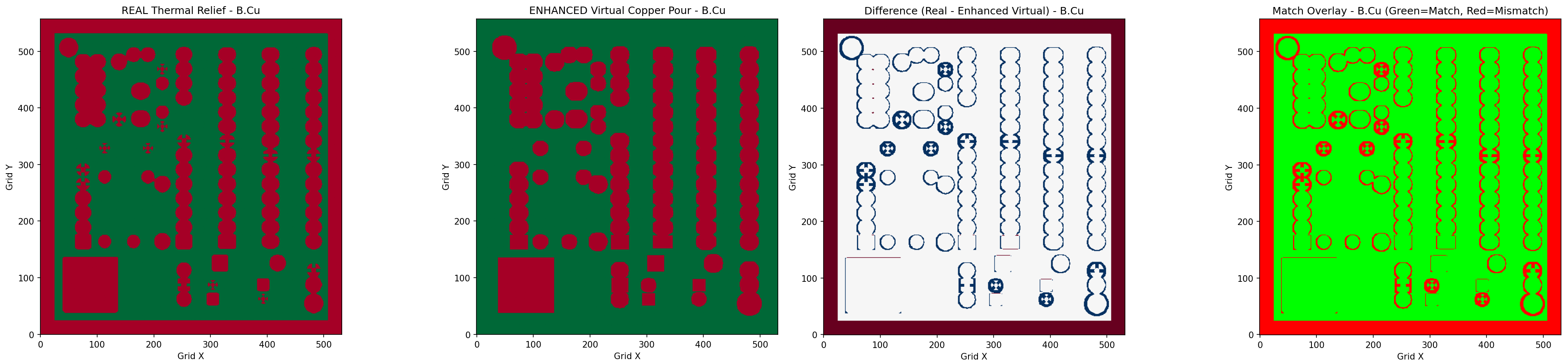
Pathfinding wasn’t the issue. There are standard algorithms for that. What really gave me a lot of trouble is figuring out where the pathfinding was valid. I’m sure someone else would have spent months going through IPC specifications to figure out where an autorouter should route traces. But I leveraged the simple fact that this data is already generated by KiCad – the copper pour itself – and just replicated it.
If there are any KiCad devs out there reading this, please implement a get_free_routing_space(int copper_layer) function in the next iteration kicad-python. Something that returns the polygon of a copper pour on boards that don’t have a copper pour, for each layer of copper.
As an initial experiment with the KiCad API, I chose to build a general purpose autorouter. Nothing fancy; just something that would route a few microcontroller breakout boards and a mechanical keyboard PCB. That’s exactly what I did. I built an autorouter that only uses wavefront expansion. And I quickly hit the fundamental limit of how useful this autorouter could be:
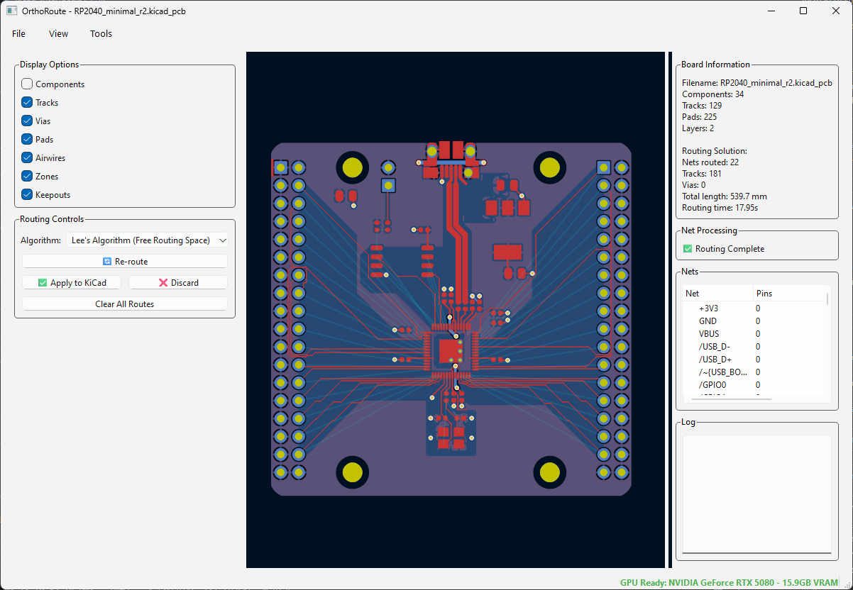
Above is a screenshot of the OrthoRoute plugin, attempting to route a board with an RP2040 microcontroller. This is the standard RP2040 breakout taken off of Raspberry Pi’s FTP server. I deleted the traces that put the GPIOs onto pin headers and pressed ‘Route Now’. The results were terrible.
This is routing with DRC awareness if you look really close. The routed traces aren’t interfering with each other, but not many traces are routed. Airwires are still there, and the routing isn’t quite as good as it could be.
For a single pass, this is fine! But autorouters don’t do a single pass. There are other techniques not implemented in this plugin like:
- Push-and-Shove routing. This technique moves existing traces to make room for new ones. It’s found in all real autorouters, but not implemented here
- Rip-up and retry. Right now we have single-pass routing. If a route fails, it’s done. Rip-up is the ability to remove ‘blocking’ or conflicting routes and try alternate paths.
- A global routing plan. When a person looks at a circuit board full of airwires, they might see ‘busses’ – a bunch of traces that all go from one component to another. It would be really smart to route these together, and route these first. I’m not doing that with my OrthoRoute. I’m just grabbing the first net from a list of unrouted nets and routing that.