
TDMA Routing on a Hypercube
Somehow, I invented a better connection machine.
My Thinkin’ Machine has 4,096 processors arranged at the vertices of a 12-dimensional hypercube. Each processor connects to 12 neighbors. There are no dedicated routers. Messages traverse the network using a time-division multiple access (TDMA) scheme. This message passing scheme has several interesting properties that turn my machine into something interesting:
- Deterministic link ownership (no collisions on a link, ever)
- Dimension-ordered routing baked into time (deadlock-avoidance and routing simplicity fall out)
- Bounded latency that’s a function of the superframe length (24 phases) and phase duration (the entire machine is synchronous)
This page explains how.
The Problem
Nodes must pass messages to each other, but the naive way of doing this – blasting out data and hoping everything works – has significant drawbacks. Consider the constraints:
- 4,096 nodes, each with 12 single-wire, half-duplex links to neighbors
- No dedicated router hardware routing logic runs on the node processors themselves
- Single wire connection links between nodes are a single wire, open drain.
- Single hardware UART per node must be remapped to different pins for different dimensions
- No collision detection or backoff the links can’t do CSMA elegantly
The original Connection Machine CM-1 solved this with dedicated routing silicon. This was an exceptionally difficult problem because Thinking Machines had to pull a Nobel laureate in Physics out of retirement to get these routers to actually work. I do not have the luxury of building custom ASICs for this project; I’m building it with microcontrollers that cost less than a dollar.
The Insight
In a hypercube, each node’s address is a binary number. Node 0x2A3 is connected to every node that differs by exactly one bit: 0x2A2 (bit 0), 0x2A1 (bit 1), 0x2AB (bit 3), and so on. To route a message from source $S$ to destination $D$, XOR the addresses:
The set bits in $\Delta$ tell you which dimensions to traverse. If bit 7 is set, the message must cross dimension 7 at some point. The number of set bits equals the number of hops.
If you traverse dimensions in a fixed order, always dimension 0 before dimension 1 before dimension 2, and so on, you get deadlock-free routing for free. This is dimension-ordered routing, and it’s a known result in the literature (see Bertsekas 1991).
Divide that clock into $2n$ phases, where $n$ is the number of dimensions. Phase $2d$ activates dimension $d$ in the low→high direction; phase $2d+1$ activates the same dimension in the high→low direction.
Now collapse this back to hardware. We have a (slowish) global clock. Each chip has an binary address. On clock phase $2d$, if that chips address bit $d$ is $0$, we map the pin for dimension $d$ connections to the hypercube UART transmit. On clock phase $2x+1$, and if that chips address bit $d$ is $1$, we map the pin for dimension $d$ connections to the UART receive.
We multiplex the UART for each chips hypercube connections through time. That’s it, that’s the entire trick. This requires a few things:
- A slow global clock, on the order of 1 to 10kHz. This is fairly easy even in a large machine because dealing with a 1kHz clock is a piece of cake.
- A microcontroller where UART peripherals can be remapped to any pin. This is difficult, but there are chips that can do it.
- Optionally, and to make things very easy, a second ‘sync’ clock that ensures the phase number is the same on all chips.
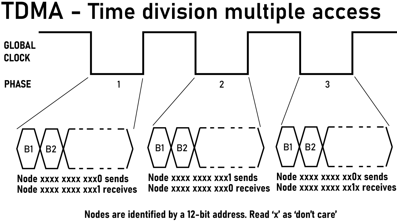
The Phase Schedule
A single communication cycle consists of 24 phases:
| Phase | Dimension | Direction | Transmitting Nodes |
|---|---|---|---|
| 0 | 0 | 0→1 | Nodes where bit 0 = 0 |
| 1 | 0 | 1→0 | Nodes where bit 0 = 1 |
| 2 | 1 | 0→1 | Nodes where bit 1 = 0 |
| 3 | 1 | 1→0 | Nodes where bit 1 = 1 |
| 4 | 2 | 0→1 | Nodes where bit 2 = 0 |
| 5 | 2 | 1→0 | Nodes where bit 2 = 1 |
| … | … | … | … |
| 22 | 11 | 0→1 | Nodes where bit 11 = 0 |
| 23 | 11 | 1→0 | Nodes where bit 11 = 1 |
In phase $2d$, nodes with address bit $d = 0$ transmit to their neighbor in dimension $d$. In phase $2d + 1$, nodes with address bit $d = 1$ transmit. Every link is active exactly twice per cycle — once in each direction — and there is never contention for a link.
Dimension-Ordered Routing
Given source $S$ and destination $D$, compute $\Delta = S \oplus D$. The message traverses dimensions in order, using the appropriate phase for each hop.
For each dimension $d$ from 0 to 11:
- If bit $d$ of $\Delta$ is not set, skip this dimension
- If bit $d$ of the current address is 0, transmit in phase $2d$
- If bit $d$ of the current address is 1, transmit in phase $2d + 1$
Because dimensions are traversed in order and phases are ordered by dimension, the sequence of phases used is always monotonically increasing. A message never waits for a phase to “come around again.”
Worked Example & Bounded Latency
An Average-Case Routing Task: Route a message from node 0x2A3 (binary 0010 1010 0011) to node 0x91C (binary 1001 0001 1100).
The set bits are: 0, 1, 2, 3, 4, 5, 8, 9, 11. That’s 9 hops.
| Hop | Current Node | Dimension | Current Bit | Phase | Next Node |
|---|---|---|---|---|---|
| 1 | 0x2A3 | 0 | 1 | 1 | 0x2A2 |
| 2 | 0x2A2 | 1 | 1 | 3 | 0x2A0 |
| 3 | 0x2A0 | 2 | 0 | 4 | 0x2A4 |
| 4 | 0x2A4 | 3 | 0 | 6 | 0x2AC |
| 5 | 0x2AC | 4 | 0 | 8 | 0x2BC |
| 6 | 0x2BC | 5 | 1 | 11 | 0x29C |
| 7 | 0x29C | 8 | 0 | 16 | 0x19C |
| 8 | 0x19C | 9 | 1 | 19 | 0x11C |
| 9 | 0x11C | 11 | 0 | 22 | 0x91C |
Phase sequence: 1, 3, 4, 6, 8, 11, 16, 19, 22. Strictly increasing. Message delivered in one cycle.
Worst-Case Routing: Route a message from node 0xFFF (binary 1111 1111 1111) to node 0x000 (binary 0000 0000 000). This is the maximum possible Hamming distance on a 12-bit address space. Every bit differs.
Because the source starts with all bits = 1, every hop uses the odd phase for that dimension (the 1→0 direction): phase $2d+1$.
| Hop | Current Node | Dimension | Current Bit | Phase | Next Node |
|---|---|---|---|---|---|
| 1 | 0xFFF | 0 | 1 | 1 | 0xFFE |
| 2 | 0xFFE | 1 | 1 | 3 | 0xFFC |
| 3 | 0xFFC | 2 | 1 | 5 | 0xFF8 |
| 4 | 0xFF8 | 3 | 1 | 7 | 0xFF0 |
| 5 | 0xFF0 | 4 | 1 | 9 | 0xFE0 |
| 6 | 0xFE0 | 5 | 1 | 11 | 0xFC0 |
| 7 | 0xFC0 | 6 | 1 | 13 | 0xF80 |
| 8 | 0xF80 | 7 | 1 | 15 | 0xF00 |
| 9 | 0xF00 | 8 | 1 | 17 | 0xE00 |
| 10 | 0xE00 | 9 | 1 | 19 | 0xC00 |
| 11 | 0xC00 | 10 | 1 | 21 | 0x800 |
| 12 | 0x800 | 11 | 1 | 23 | 0x000 |
Phase sequence: 1, 3, 5, 7, 9, 11, 13, 15, 17, 19, 21, 23. Strictly increasing. Message delivered in one cycle.
Now route the opposite direction from node 0x000 (binary 0000 0000 000) to node 0xFFF (binary 1111 1111 1111).
Because the source starts with all bits = 0, every hop uses the even phase for that dimension (the 0→1 direction): phase $2d$.
| Hop | Current Node | Dimension | Current Bit | Phase | Next Node |
|---|---|---|---|---|---|
| 1 | 0x000 | 0 | 0 | 0 | 0x001 |
| 2 | 0x001 | 1 | 0 | 2 | 0x003 |
| 3 | 0x003 | 2 | 0 | 4 | 0x007 |
| 4 | 0x007 | 3 | 0 | 6 | 0x00F |
| 5 | 0x00F | 4 | 0 | 8 | 0x01F |
| 6 | 0x01F | 5 | 0 | 10 | 0x03F |
| 7 | 0x03F | 6 | 0 | 12 | 0x07F |
| 8 | 0x07F | 7 | 0 | 14 | 0x0FF |
| 9 | 0x0FF | 8 | 0 | 16 | 0x1FF |
| 10 | 0x1FF | 9 | 0 | 18 | 0x3FF |
| 11 | 0x3FF | 10 | 0 | 20 | 0x7FF |
| 12 | 0x7FF | 11 | 0 | 22 | 0xFFF |
Phase sequence: 0, 2, 4, 6, 8, 10, 12, 14, 16, 18, 20, 22. Strictly increasing. Message delivered in one cycle.
Bounded Latency
The maximum number of hops in a 12-dimensional hypercube is 12 (all bits differ). The maximum number of phases is 24. Every message — regardless of source, destination, or network load — completes within one 24-phase cycle. This isn’t worst-case latency, it’s the latency for every possible message between every possible pairs of nodes in the hypercube.
Wall-clock latency depends on phase duration:
| Phase Rate | Phase Duration | Cycle Duration | 12-Hop Latency |
|---|---|---|---|
| 1 kHz | 1 ms | 24 ms | 24 ms |
| 10 kHz | 100 µs | 2.4 ms | 2.4 ms |
| 100 kHz | 10 µs | 240 µs | 240 µs |
At 10 kHz phase rate with 1 Mbps baud, each phase carries ~100 bits — enough for a 10-byte payload plus header. The entire machine can exchange data at 2+ Gbps aggregate bandwidth with deterministic 2.4 ms latency.
What Falls Out
The Connection Machine was famous beyond its blinkenlights for what fell out of the architecture. A bitonic sort algorithm is perfect for hypercube clusters of computers. Using the NEWS grid of the Connection Machine, intelligence services had the fastest image processing machine on the planet. This TDMA scheme is the same thing; really cool stuff just falls out of the architecture:
No collision detection. Two nodes never try to transmit on the same link simultaneously.
No backoff or retries. Collisions don’t happen, so recovery logic doesn’t exist.
No buffering beyond one message. A node receives at most one message per link per phase. The “buffer” is a single register.
No deadlock. Dimension-ordered routing is provably deadlock-free, and the phase schedule enforces dimension ordering automatically.
Trivial routing logic. The algorithm at each node:
void route_message(uint16_t dest, uint8_t *payload) {
    uint16_t delta = my_addr ^ dest;
    for (int dim = 0; dim < 12; dim++) {
        if (delta & (1 << dim)) {
            int phase = 2 * dim + ((my_addr >> dim) & 1);
            wait_for_phase(phase);
            transmit(dim, payload);
            return; // next hop handles remaining dimensions
        }
    }
}
That’s it. The complexity is in the schedule, not the silicon.
Why This Works Here
This scheme exists because of constraints. The project couldn’t afford dedicated router ASICs. I couldn’t find a microcontroller with 12 hardware UARTs. The one UART I had could be remapped to different pins at runtime. TDMA solves all of these problems simultaneously. One UART handles all 12 dimensions because we’re only using one dimension at a time. There’s no router hardware because the TDMA schedule is the router.
The original Connection Machine CM-1 used dedicated routing hardware because the constraints were different: custom silicon, DARPA budget, and a goal of supporting arbitrary asynchronous communication patterns. The routers were complex because they were solving the general case. My workloads are synchronous. Compute, exchange, compute, exchange. For that pattern, the general case is unnecessary overhead. Lockstep TDMA is a feature, not a limitation.
There is one gigantic, glaring problem with this idea. A naive interpretation of this routing scheme would complain that I just reduced the potential speed of the machine by a factor of 24. This is true, but it’s lacking context. This paper from NASA Ames in 1990 assessed the Connection Machine from a programming standpoint, and the takeaway is not good.
The NASA assessment of the Connection Machine says, “irregular communication through the router is very expensive and should be sparingly used.” Also, _“The router is the key to the CM. The current machine has a router that runs at roughly 1% of floating point speed. This makes router-intensive algorithms unattractive in terms of their performance.”
The CM-1’s general purpose router, the thing that made it flexible, was so slow that NASA’s assessment was basically, “don’t use it”. The machine could route messages arbitrarily and asynchronously but in practice nobody used it because it was a hundred times slower than compute.
The TDMA scheme gives up the theoretical capability of arbitrary asynchronous routing, but that was unusable to begin with. In exchange, I get structured communication that I can actually use every cycle.
This isn’t new
All of this isn’t new. US Patent 5,420,982 Hyper-cube network control system having different connection patterns corresponding to phase signals for interconnecting inter-node links and between input/output links. uses a clock and crossbars to give the nodes of a hypercube a means to communicate. There’s a massive caveat here – this was from 1994, so sure we can use a discrete crossbar instead of an FPGA. nothing new there – but compared to my machine, the clock is wrong. Patent 5,420,982 uses a clock with 2^n phases, where n is the number of nodes in a hypercube. My machine uses a clock with 2n phases. For a 12-dimension machine, this means patent 5,420,982 has 4096 clock phases, mine has 12.
The scheme in patent 5,420,982 allows for any-to-any node communication, where my machine does not allow for any node to communicate with any other node. The patent’s scheme is 170× slower per round with a 12-dimension machine, and it gets slower as the dimension number grows. Nothing related to this patent was ever built, probably related to the fact that as now and in 1994, crossbars are expensive and a really slow hypercube isn’t interesting.
Patent 5,420,982 is just someone looking at a Connection Machine, noticing routers are too expensive, and correctly realizing routers can be replaced with a global clock.
My Context
This isn’t new, and there’s a list of references demonstrating that in the section below. There’s a lot of relevant literature, and virtually none of it has resulted in a new machine.
The original Connection Machine CM-1 solved a slightly different problem with its routers. The CM-1 solved general purposes communication under unpredictable traffic. This required buffers, arbitration, and deadlock avoidance. In the CM-1, there is a lot of silicon dedicated to simply passing messages between nodes.
This TDMA scheme requires effectively zero silicon, and only needs a relatively slow global clock. I lose the idea that ‘any node can talk to any dimension at any time’, but if you zoom out to the superset of the phase clock that doesn’t really matter at all. It’s just a small implementation detail.
Am I the first person to think of this? I have no idea.
References
-
Shridhar B. Shukla, “Scheduling Pipelined Communication in Distributed Memory Multiprocessors for Real-Time Applications,” ISCA ‘91, pp. 222–231 (1991). The grandfather of the whole idea. A compile-time schedule for a hypercube or torus, explicitly called “deadlock-free, contention-free, and does not load the intermediate node memory.” Shukla uses the phrase “time division multiplexing.” He cites Stout. He cites Bertsekas. The entire algorithmic content of my machine is sitting in one ACM paper from 1991, and almost nobody has touched it since.
-
Alan Edelman, “Optimal Matrix Transposition and Bit Reversal on Hypercubes: All-to-All Personalized Communication,” Journal of Parallel and Distributed Computing, 11(4), 328–331 (1991). The money sentence: “if every other node performs the same sequence of actions in its own relativized coordinate system, there will be no contention for communications channels.” Read in 2026 that’s a textbook description of TDMA. Read in 1991 it’s an algorithms paper about matrix transpose. Edelman ran it on a real CM-2; the Connection Machine was effectively executing collision-free schedules in 1990, it just paid for an expensive router to enforce them instead of letting the topology do it for free.
-
Shahid H. Bokhari, “Multiphase Complete Exchange on a Circuit Switched Hypercube,” NASA/ICASE Technical Report (1991); later in Parallel Processing Letters. All-to-all personalized communication on the Intel iPSC-860, scheduled as a sequence of partial exchanges on subcubes of varying dimension. So in 1991 there was a guy with hands on an actual circuit-switched commercial hypercube, running multi-phase scheduled communication, and writing it up for NASA. Nine years before Lee, Liu, and Jordan “proposed” the TDM hypercube.
-
Kyungsook Y. Lee, Guoping Liu, and Harry F. Jordan, “TDM Hypercube and TWDM Mesh Optical Interconnections,” Journal of Parallel and Distributed Computing, 60(11), 1337–1363 (2000). The paper that names the TDM-cube. log₂(N) time slots, fixed-wavelength transmitter per node, equations and block diagrams that map onto my schematic with embarrassing fidelity. Their machine was optical, hypothetical, and never built. Mine is microcontrollers, real, and on my desk. Same idea, twenty-six years apart.
-
Risto T. Honkanen, “Scheduled Routing in an Optical Hypercube,” ISPDC 2008, pp. 300–305. DOI: 10.1109/ISPDC.2008.16. A “systolic routing protocol based on cyclic changes of states of routers and scheduled sendings of packets” that guarantees “all packets injected into the routing machinery reach their targets without collisions.” Replace “optical” with “RS-232 at 2 Mbps” and “router” with “UART pin remap” and you have my project. Honkanen wrote a whole series of these between 2003 and 2010. Almost nobody cited them.
-
Chuck Thacker, “Hypercube Routing Scheme,” DEC SRC Technical Note 2000-001 (January 2000). Thacker independently arrives at bit-flip hypercube addressing and XOR-based routing in a small four-dimensional network, derived from first principles in a one-page memo. Reading this is what convinced me there is no original way to think about hypercubes. Everybody who works on one reinvents the same handful of tricks.
-
US Patent 5,420,982. “Hyper-cube network control system having different connection patterns corresponding to phase signals for interconnecting inter-node links and between input/output links.” Filed 1993, granted 1995, expired ~2015. The closest thing in the patent literature to what I’m doing. Bit train generator producing 2ⁿ phase signals, switching means selecting 2ⁿ connection patterns per phase, node designations where neighbors differ by one bit, control rule keyed on parity of 1-bits in the node ID. Every block diagram in this patent looks like a block diagram I drew. It expired without ever being commercialized, but you can’t unread it.
-
US Patent 5,367,636. “Hypercube processor network in which the processor identification numbers of two processors connected to each other through port number n vary only in the nth bit.” Filed 1989, granted 1994, expired. The addressing scheme of my machine, claimed verbatim. Up to 14 full-duplex I/O ports per node, dimensions to 13. Whatever you think you came up with, somebody at one of the big iron shops thought of it first and put it in a patent application.
-
US Patent 5,255,368. “Method for selecting data communications paths for routing messages between processors in a parallel processing computer system organized as a hypercube.” Filed 1991, granted 1993, expired. Claim 1 spells out the routing algorithm: “form a distance by exclusive or-ing a starting node address with destination node address,” then walk the differing bits. Strip the patent-attorney prose and that’s a
forloop you’d write at 2am. -
US Patent 4,814,980. “Concurrent hypercube system with improved message passing.” Filed 1986, expired ~2006. The hardware skeleton: bidirectional links per dimension, FIFO at each node, a clocking line between neighbors, supervisory signals indicating FIFO empty/full. There’s a 1986 patent that already covered the physical layer of what I’m building, twenty years before the parts I’m using even existed.
-
US Patent 6,456,588. “Hypercube routing and restoration in telecommunications networks.” Filed 1997, granted 2002, expired ~2017. XOR-based hypercube routing for telecom failover. Different application, same algorithm. Sleeping in a patent file for two decades.
-
Hayashi et al., US 4,918,626 / US 5,339,396 / US 5,517,619 (Hitachi, priority 1987–1988, all expired); related Japanese application JP 2512661B2 covering non-binary hypercubes. The Hitachi family. Crossbars and interconnects for parallel processors with various flavors of hypercube switching. None of these is exactly what I’m doing, but together they cover most of the territory around it. Read the file wrappers and you can see every place I would have collided with a portfolio had I tried this in 1995.
-
Hermann Kopetz, Real-Time Systems: Design Principles for Distributed Embedded Applications, Kluwer Academic Publishers (1997). ISBN 978-0792398943. If TTP/C is the paper, this is the book. Kopetz lays out the entire theory of time-triggered architectures — global time base, sparse-time model, static schedule, fail-silent components — over 300 pages. Read this before you build any kind of deterministic distributed system, because Kopetz has thought about your edge case already.
-
Gerardine Leen and Donal Heffernan, “TTCAN: A New Time-Triggered Controller Area Network,” Microprocessors and Microsystems, 26(2), 77–94 (2002). The canonical TTCAN paper. CAN bus plus a TDMA matrix cycle for deterministic timing in automotive control. Capped at 1 Mbit/s with limited cable length, but the schedule concept is identical to what I’m doing on a different physical layer. Worth reading just to see how the automotive industry quietly solved this thirty years ago and called it Tuesday.
-
Hermann Kopetz, Astrit Ademaj, Petr Grillinger, and Klaus Steinhammer, “The Time-Triggered Ethernet (TTE) Design,” ISORC 2005; now standardized as SAE AS6802. TTEthernet. TDMA on top of Ethernet, scheduled by switches that know the global time. Now flies on the Orion spacecraft. The aerospace world solved the deterministic-distributed-systems problem a long time ago using exactly the trick I’m using; I just have a different topology underneath and a smaller budget.
-
Kees Goossens, John Dielissen, and Andrei Rădulescu, “Æthereal Network on Chip: Concepts, Architectures, and Implementations,” IEEE Design & Test of Computers, 22(5), 414–421 (2005); and Kees Goossens and Andreas Hansson, “The Æthereal Network on Chip after Ten Years: Goals, Evolution, Lessons, and Future,” DAC 2010. The on-chip TDM network from Philips/NXP. Per-slot connection tables in each router, contention-free routing, no arbitration logic. Goossens and team spent a decade shipping this in real silicon. Different topology from a hypercube, same fundamental abstraction: precompute the schedule, throw away the routers. The 2010 retrospective is the playbook for shipping a TDM network in silicon.
-
Quentin F. Stout and Bruce Wagar, “Intensive Hypercube Communication: Prearranged Communication in Link-Bound Machines,” Journal of Parallel and Distributed Computing, 10(2), 167–181 (1990); preliminary version in Hypercube Multiprocessors 1987. The paper. “Communication pattern known in advance by all processors, all messages are of the same size, message headers are not needed because all nodes know the task being performed, and all nodes can use all communication links simultaneously.” That is, to a comma, the algorithmic content of my machine — written in 1987, published in 1990, and almost completely ignored for thirty-five years. Stout assumed a working network and optimized message patterns; I’m using his optimization to design the network in the first place.